49
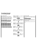
T A X I C U P : 1
F U N C T I O N ?
9
5
ENTER
↓↓
T A X I C U P : 1
M O D U L A T I O N P C M
INC
↓↓
T A X I C U P : 1
M O D U L A T I O N P P M
ENTER
↓↓
T A X I C U P : 1
p o w e r s w o f f
Switch the power off, and then on again
↓↓
T A X I C U P : 1
9 . 6 V P P M
ENTER
↓↓
T A X I C U P : 1
F U N C T I O N ?
10.) Adjusting the Direction of Servo Rotation
For the ensuing adjustments you now require a model
with a ready to operate installed radio set. The servos
should be wired to the receiver as follows:
Channel 1 = Engine Throttle
Channel 2 = Ailerons
Channel 3 = Elevator
Channel 4 = Rudder
Turn the transmitter and receiver on now and check
the function of the control surfaces. Most likely one or
other of the servos will be found to rotate in the wrong
direction (it would be matter of sheer luck if not). To
correct the direction of rotation of a servo moving in
the wrong direction, call servo reversing code 11:
ENTER
1
1
ENTER
The display now indicates the direction of rotation of
all servos. Correct the direction of rotation by entering
the corresponding channel number so all control
surfaces and the throttle move in the right direction.
Terminate all input using the
ENTER
key.
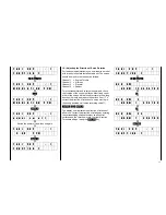
T A X I C U P : 1
F U N C T I O N ?
1
1
ENTER
↓↓
R E V . S W
N O R M 1 2 3 4 5 6 7 8 9
2
↓↓
R E V . S W 2
N O R M 1 4 5 6 7 8 9
3
↓↓
R E V . S W 2 3
N O R M 1 4 5 6 7 8 9
ENTER
↓↓
T A X I C U P : 1
F U N C T I O N ?
Summary of Contents for mc-18
Page 1: ...1...
Page 10: ...Block Diagram NORMAL 10...
Page 11: ...Block Diagram NORMAL DIFF 11...
Page 12: ...Block Diagram DELTA DIFF 12...
Page 13: ...Block Diagram UNIFLY DIFF 13...
Page 14: ...Block Diagram Quadro Flap 14...
Page 15: ...Block Diagram F3B 3 wing servos 15...


