background image

52

Control settings

Basic procedures for assigning transmitter controls and switches

In addition to the two dual-axis stick units for the control 
functions 1 to 4, the mx-16s is fi tted as standard with a 
range of supplementary controls:

•  Two INC / DEC buttons: CTRL 5 and 6 (“transmitter 

controls 5 … 6”)

•  One three-position switch: SW 6/7 (assigned to “Con-

trol 8” in this menu)

•  One rotary proportional knob: CTRL 7 (“transmitter 

control 7”)

•  One push-button: SW 4 / PB 8 (“SW 4” or “SW 8”)
•  Three two-position switches: SW 1 to SW 3 (“SW1 … 

3”)

The two dual-axis stick units directly affect servos con-
nected to receiver outputs 1 … 4 (assuming that you 
have set up a newly initialised model memory with the 
model type “Helicopter”). In contrast, the “supplemen-
tary” transmitter controls listed above are inactive when 
the transmitter is in its default state (as delivered).
As already mentioned on page 14, this means that the 
transmitter in its basic form only controls servos connec-
ted to receiver outputs 1 … 4 using the primary sticks. 
Any servos connected to receiver sockets 5 … 8 simply 
stay at their centre point when you operate the associa-
ted transmitter controls.
This may seem rather inconvenient at fi rst sight, but it 
is the only way to ensure that you can select any of the 
“supplementary” transmitter controls for any task you 
like, and that you are not required deliberately to “pro-
gram away” the transmitter controls which are not re-

quired for a particular model.

Unless it is inactive, any superfl uous transmitter 
control will have an effect on your model if you ope-
rate it by mistake, i.e. unless you have assigned no 
function to it.

That is why you can select these “supplementary” trans-
mitter controls with complete freedom in the “Control 
settings” menu and assign them to any function input 
(see page 24) you like, as this method means that the 
transmitter meets your own requirements exactly. This 
also means that each of these transmitter controls can 
be set to operate several function inputs simultaneous-
ly. For example, the same toggle switch SW X which you 
assign to an input in this menu, can also be assigned 
as the On / OFF switch controlling the “Timers” in the 
»

Base settings

« menu.

Note:
If you switch models, the current positions of the INC / 
DEC buttons (CTRL 5 + 6) assigned to inputs 5 … 8 are 
stored separately for each memory, i.e. the settings are 
not lost.

Basic procedure

1. Hold the 

SELECT

 button pressed in, and select the 

appropriate input E5 … E8 using the right-hand ro-
cker button.

2.  Use the right-hand rocker button to select 

SEL

SYM


or 

ASY

 so that you can carry out the adjustments 

you wish to make.

3. Press the 

SELECT

 button: the input fi eld you wish to 

modify is highlighted.

4.  Operate the transmitter control you wish to use, and 

set the desired value using the right-hand rocker but-
ton.

5. Press the 

SELECT

 button to conclude the input pro-

cess and return to the function fi eld.

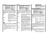
Column 2 “Assigning transmitter controls and swit-
ches”

Hold the 

SELECT

 button pressed in, and select one of 

the inputs using the right-hand rocker button.
Use the right-hand rocker button to select 

SEL

, or (if 

SEL

 is already highlighted) press the 

SELECT

 button to 

move to the assignment facility …

… and move the appropriate transmitter control (CTRL 
5 to 7), or operate the selected switch (SW 1 to 4, 6/7, 
8). Note that the transmitter emits a “beep” when it de-
tects the two INC / DEC buttons (CTRL 5 and 6) and the 
rotary proportional control, i.e. they need to be operated 
for longer than the other controls. If the travel is not suf-
fi cient for the transmitter to detect it, move the control in 
the opposite direction.
If you assign one of the two-position switches, then this 
control channel works like an On / Off switch. It is then 
possible to switch to and fro between two end-point va-
lues using this simple switch, e.g. searchlight ON / OFF. 
The three-position switch SW 6/7, which you will fi nd in 
the »

Control settings

« menu as “Control 8”, also provi-

des a centre position.
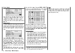
Pressing the 

CLEAR

 button with the switch assignment 

activated – see illustration above – resets the input to 
“free”.

Tips:
When assigning the switches please take care to set 
them to the appropriate direction of travel, and ensu-
re that all inputs not required are left at or set to “free”, 

Control settings – Model helicopter

Summary of Contents for MX-16S

Page 1: ...1...

Page 2: ...on of terms 24 Assigning switches and transmitter controls 25 Digital trims 26 Position display INC DEC buttons 27 Servo display 27 Fixed wing model aircraft 28 Receiver socket assignment 29 30 Model...

Page 3: ...ient tempera tures i e within the range 15 C to 55 C Avoid subjecting the equipment to shock and pressu re Check the units at regular intervals for damage to ca ses and leads Do not re use any item wh...

Page 4: ...to the battery manufacturer s instructions and don t leave the batteries on charge for longer than stated Do not leave batteries on charge unsupervised Never attempt to recharge dry cells as they may...

Page 5: ...spark plugs and plug caps and shielded ignition leads Keep the receiving system an adequate distance away from the ignition system Static charges Lightning causes magnetic shock waves which can in te...

Page 6: ...transmit ter a simple self explanatory process Mixers and other functions can be displayed in graphic form and this is extraordinarily helpful The beginner soon becomes familiar with the wide ran ge o...

Page 7: ...such as switches and proportional controls Unrestricted assignment of all switches to switched functions simply by operating the desired switch Twelve model memories for storing all model specific pr...

Page 8: ...R600 R600 light R700 and C6 C8 SB6 SYN 40S SR6SYN Servo travel adjustment 150 for all servo chan nels variable for each end point separately Single Side Servo Throw Sub trim for fine tuning the neutra...

Page 9: ...ner leads Replacement part Order No Description 3100 6 Telescopic aerial for mx 16s transmitter Operating voltage 4 8 6 V Current drain approx 24 mA Spot frequencies 35 MHz 61 282 182 191 Spot frequ 4...

Page 10: ...ur part The transmitter charge socket is not protected against short circuit and or reversed polarity It is therefore essential to use the correct procedu re when connecting the charge lead first conn...

Page 11: ...plies in particular if you are using an auto matic charger designed for NiCd batteries to rechar ge the standard NiMH battery You may need to adjust the Delta Peak trigger volta ge if your charger pro...

Page 12: ...section on page 10 Locate the six recessed screws on the back on the transmitter and undo them using a PH1 size cross point screwdriver see drawing right Hold the two case sec tions together with you...

Page 13: ...ow find the ratchet spring also supplied and fix it to the plastic pillar using the black self tapping screw supplied You can now set the strength of the ratchet spring on the side of the hexagonal bu...

Page 14: ...21 Neckstrap 20 mm wide 70 Neckstrap 30 mm wide SW 6 7 three position switch Description of transmitter transmitter controls INC DEC buttons CTRL 5 and 6 Each time you press the button the servo trave...

Page 15: ...he appropria te menus If you are connecting the transmitter to a flight simu lator for example these settings are found in the Modulation line of the Base settings menu PPM is usually required If you...

Page 16: ...l you can for example prepare your model ready to fly without causing interference to other pi lots Another advantage is that the transmitter s cur rent drain is reduced to only about 65 mA since the...

Page 17: ...17...

Page 18: ...ange CLEAR button erases or resets to default value Model name Memory 1 12 Battery voltage if voltage falls below a particular value a warning display appears see images at top right and an audible wa...

Page 19: ...pressed in you can leaf through the menu lines within the indi vidual set up menus using the right hand rocker button symbolised by above and below the two buttons Buttons to the right of the screen a...

Page 20: ...itter may malfunction with possible damage to the RF mo dule When you wish to control a model it is fundamentally es sential to screw the ten section telescopic aerial into the transmitter and extend...

Page 21: ...as you will be highly unlikely to be able to re activate the RF signal quickly enough since the transmitter always responds with the security query RF signal onYES NO when switched on Adjusting screen...

Page 22: ...on you only need to do this if you change channels 4 If the LED flashes slowly after a few seconds it is un able to lock onto the transmitter frequency Check the transmitter then repeat steps 1 to 3...

Page 23: ...and tigh tened properly The picture on the right shows how to install a servo correctly The brass spacers should be pushed into the rubber grommets from the underside 5 The servo output arms must be...

Page 24: ...on the circuit board where the transmitter control is connected The two menus Stick mode and Control settings af fect the course of the signal after these points and it is possible and likely that th...

Page 25: ...tch is only ON as long as the button is held pressed in Note Every time you switch the transmitter on switch 4 al ways defaults to the OFF position Transmitter control switches Many functions are best...

Page 26: ...on to cut off trim as described under Fixed wing models on the left this time in conjunction with the Throttle limit function see page 54 while the thrott le limit slider is in the bottom half of its...

Page 27: ...and for model helicopters Bar 1 Collective pitch or roll 2 or nick 2 servo Bar 2 Roll 1 servo Bar 3 Nick 1 servo Bar 4 Tail rotor servo gyro Bar 5 Nick 2 servo free channel Bar 6 Throttle servo or sp...

Page 28: ...wing As standard the program con tains the appropriate mixer functions for the two servos Up to three flight phases can be programmed in each of the 12 model memories The digital trim positions are st...

Page 29: ...the servo sequence at the receiver outputs as shown in the diagram on the left However an alter native method is to use the Receiver output sub menu of the Base settings menu see page 41 Dif ferent m...

Page 30: ...elevator reversed Model type Servo rotating in wrong direction Remedy V tail Rudder and elevator reversed Rudder correct elevator reversed Elevator correct rudder reversed Delta flying wing Elevator...

Page 31: ...31 Fixed wing models Installation and connections...

Page 32: ...rotor with 5 point curve 4 Gyro The throttle limit function in the Control settings menu provides an effective means of starting the mo tor in any flight phase By default the proportional rotary cont...

Page 33: ...Synthesizer MICRO SUPERHET Best Nr 7052 Kanal 60 282 182 191 f r das 35MHz 35MHz B Band SCAN LED Made in Malaysia R 1 6 FM S C A N Receiver battery Installation notes The servos must be connected to...

Page 34: ...of the empty model memories 1 to 12 then press ENTER or SELECT You are now invited to select the basic model type i e either Fixed wing or Helicopter Use the right hand rocker button to select the app...

Page 35: ...35 Program description Reserving a new memory...

Page 36: ...n to select from the list the model you wish to erase then press SELECT or ENTER The program re sponds with the security query model to be erased If you answer NO the process is interrupted and you ar...

Page 37: ...ontains model data When you confirm the selected model memory by pres sing the ENTER or SELECT button the security query appears model to be copied Note If you wish to erase the currently active model...

Page 38: ...pends on your individual preferences and flying style When you select stick mode you will see SEL at the bottom edge of the screen Press the SELECT button and the current stick mode is highlighted inv...

Page 39: ...nu the Brake NN mixers are activated Idle re The idle position of the throttle air brake stick C1 is rear i e towards the pilot Idle fr The idle position of the throttle air brake stick C1 is in front...

Page 40: ...n of times can also be selected CLEAR 0 or 00 Procedure 1 Select the SEL field with the right hand rocker button 2 Press SELECT 3 Select the required time in the highlighted minutes and seconds fields...

Page 41: ...ENTER button to move to the next page of the display Here you can assign the con trol channels for servos 1 8 to any receiver out put you wish to use However please note that the dis play in Servo di...

Page 42: ...the se options you select depends on your individual prefe rences and flying style When you select stick mode you will see SEL at the bottom edge of the screen Press the SELECT button and the current...

Page 43: ...moved axially by two roll servos for collective pitch control pitch axis control is de coupled by a me chanical compensating rocker HEIM mechanics 3sv 2roll A symmetrical three point swashplate lin k...

Page 44: ...mixer etc The meaning is as follows front minimum collective pitch when the collective pitch stick C1 is in front away from you rear minimum collective pitch when the collective pitch stick C1 is back...

Page 45: ...tion When the set time has elapsed the ti mer does not stop but continues to run to allow you to read off the time elapsed after reaching zero To make this clear the over run time is shown highlighted...

Page 46: ...ll work correctly in conjunction with receiving systems and radio control equipment made by other manufacturers tion you wish to change then press ENTER or SELECT Now you can assign the desired servo...

Page 47: ...47 Base settings Model helicopter...

Page 48: ...uired 3 Press the SELECT button the corresponding input field is highlighted inverse video 4 Set the appropriate value using the right hand rocker button 5 Finally press the SELECT button again to con...

Page 49: ...ch to the appropriate end point when you press the SELECT button the highlighted servo travel field swit ches between the left field negative direction and the right field positive direction Pressing...

Page 50: ...ments exactly This also means that each of these transmitter controls can be set to operate several function inputs simultaneous ly For example the same toggle switch SW X which you assign to an input...

Page 51: ...8 Use the right hand rocker button to select SYM or ASY in the Travel column and press the SELECT button to activate travel adjustment You can now use the right hand rocker button to set the control t...

Page 52: ...itch SW X which you assign to an input in this menu can also be assigned as the On OFF switch controlling the Timers in the Base settings menu Note If you switch models the current positions of the IN...

Page 53: ...ol settings Model helicopter to eliminate the possibility of errors if unused transmitter controls are operated accidentally You can alter the effective end points of an assigned switch by adjusting s...

Page 54: ...of throttle travel provides a conve nient means of starting and stopping the motor Howe ver it also forms an effective method of recording flight times via the control switch G3 if the latter is set...

Page 55: ...acts as idle trim on the throttle limit in the bottom half of the travel of the throttle limit cont rol i e the marker is only set and stored within this ran ge For this reason the C1 trim display is...

Page 56: ...h the result that the angular travel of the output device increa ses disproportionately as stick travel increases Like Dual Rates the Expo setting applies directly to the corresponding stick function...

Page 57: ...lighted field to set separate values for each of the two switch positions Pressing CLEAR in the highlighted field resets an alte red value to 0 In these examples the Dual Rate value is 100 in each cas...

Page 58: ...ver You can compensate for this effect by setting an Expo value greater than 0 with the result that the angular travel of the output device increa ses disproportionately as stick travel increases Like...

Page 59: ...value other than 0 in the other switch posi tion To change the Expo value first select the right hand SEL field then use the right hand rocker button in the highlighted field to set separate values f...

Page 60: ...hidden If you select the Phase trim menu with this basic ar rangement i e without setting up flight phases you will find just the normal line on the screen whose pre set values of 0 are not usually ch...

Page 61: ...ith camber chan ging flaps and you have not entered any flap servos in the Base settings menu all the flap mixers in the program are automatically suppressed as are the Bra ke NN mixers if you enter I...

Page 62: ...It is easily possible to vary the degree of differential wi thout affecting the travel of the up going aileron In one extreme it is possible to suppress the down aileron de flection completely i e onl...

Page 63: ...1 4 is assigned to this function the mixer can be switched on and off in flight so that you can con trol the ailerons and rudder separately if and when you so desire ail flaps Aileron flap This mixer...

Page 64: ...full span strip ailerons which also double as camber changing flaps the two mixers Brake ailerons and Brake elevator can be com bined for glide path control In this case up flap is ap plied but the fl...

Page 65: ...surfaces In this case you really should use differential reduction it at all possible This reduces the degree of aileron dif ferential when you invoke the butterfly setting using the airbrake stick D...

Page 66: ...d to a variable pre defi ned value A value must be entered in the Gyro and Input 8 li nes press the SELECT button then change the value in the highlighted field using the right hand rocker button Pres...

Page 67: ...utton can now be used to change the current curve value in the highlighted field to any value within the range 125 to 125 without affecting the adjacent points In this example we have moved reference...

Page 68: ...w typical 3 point thrott le curves for different flight phases such as hover aero batics and 3 D flying Typical throttle curves for different flight phases Notes on using the Throttle limit function W...

Page 69: ...end points determined for each flight pha se gyro gain can be varied proportionally between mi nimum and maximum by means of a transmitter cont rol assigned in the Gyro line in the Control settings me...

Page 70: ...entre position of the throttle collective pitch stick The diagram shows a curve with a slightly altered throttle setting below the hover point at the centre of stick travel Idle setting and throttle c...

Page 71: ...eed too low Remedy increase the value for the throttle servo parameter at Point 3 of the stick travel in the Ch1 throttle mixer as shown in the graph b Rotational speed too high Remedy increase the bl...

Page 72: ...generally free to swivel and they may This diagram only shows the changes to the collective pitch maximum value full deflection of the collective pitch stick i e the value at Point 5 Conversely if mot...

Page 73: ...tion in which case they might respond by swinging far out of their normal position perhaps resulting in a boom strike Once the motor is running you should slowly increase system rotational speed using...

Page 74: ...cal line to Point 5 using the transmitter stick Start by setting a value which is about 10 to 20 higher than the normal collective pitch maximum any more than this and the helicopter may balloon up ag...

Page 75: ...With the transmitter and receiving system switched on select the Autorotation flight phase Fold both tail rotor bla des down and change the blade pitch angle to zero de grees using the Tail rotor menu...

Page 76: ...nts In software terms the default setting for any freely pro grammable mixer is that it is constantly switched on but it is also possible to assign an optional ON OFF switch to it However since there...

Page 77: ...lighted inverse video 3 Define the mixer input from using the right hand ro cker button 4 Press SELECT move to SEL under the to column using the right hand rocker button and press SE LECT once more Th...

Page 78: ...o be employed as landing flaps i e when the associated transmitter control is operated they deflect down only However this flap movement requires an ele vator trim correction to counteract the resulta...

Page 79: ...witches to the second screen page If this display does not appear you have not activated the mixer by operating the assigned external switch in this case 1 To correct this operate the switch The solid...

Page 80: ...ed to receiver output 3 to slight up trim when the tow release is closed In the screen familiar from page 77 we have set up the third linear mixer to accomplish this using the switch channel S as the...

Page 81: ...the screen shot above The pre set value is 61 in each case but the value can be varied within the range 100 to 100 using the right hand rocker button af ter pressing the SELECT button Pressing the CLE...

Page 82: ...d channel 1 to 8 and press the SELECT button in or der to switch between hold and position mode Select the STO field on the screen at bottom right using the right hand rocker button and then simultane...

Page 83: ...83 Fail safe...

Page 84: ...In such cases the servo output arms should be offset forward by one spline relative to the neutral point i e to wards the leading edge of the wing and fitted on the servo output shaft in that positio...

Page 85: ...ent if you choose none no motor otherwise they are suppressed In addition to these basic matters you will certainly need to consider carefully how best to control any auxiliary functions featured on y...

Page 86: ...rst consider none no motor in the following programming example In the next two lines you select the basic arrangement of the servos in the model and inform the transmitter of your choice Tail type No...

Page 87: ...f aileron differential is to eliminate adverse yaw When a model aircraft turns the down going aileron pro duces more drag than the up going one if both move th rough the same angle and this causes the...

Page 88: ...recommend that you reduce the travel of the flaps in the Control settings menu as this gi ves finer control of the flap positions using the selected transmitter control The remaining options in the Wi...

Page 89: ...89 Programming examples Fixed wing model...

Page 90: ...select the desired line A further press on SELECT activates Switch transmitter control assignment Now turn the knob of the rotary proportio nal control After a brief delay the entry Transmitter con tr...

Page 91: ...itch transmitter control assi gnment Now move the switch SW 6 7 The highlighted field now shows Transmitter control 8 In the third column you can adjust servo travel to suit the speed controller you a...

Page 92: ...ody To achieve this you may have to move to the menu Servo settings page 48 and reverse the direction of servo 1 For safety s sake you should check this setting now be fore you continue with the progr...

Page 93: ...u now switch back to the Servo display menu and move just the C1 stick you will see that the bar display for Channel 1 either remains at around 100 while the displays for channels 2 5 and also the fla...

Page 94: ...ceding pages you have decided on Examp le 4 or you are using the C1 stick throttle brake stick to control motor power independently of this program ming example then you can use the associated control...

Page 95: ...mmend that the switch direction should match the phase numbering as shown in the left hand illustration for example Phase 2 is back from the centre position while Phase 3 is forward Select the appropr...

Page 96: ...se of the Free mixers menu which offers the advantage of asymmetrical and or non linear curves In this example we will connect two rudders in parallel The second rudder could be connected to receiver...

Page 97: ...throttle min front rear trim acts only at idle ran ge Tail type Delta flying wing or Normal type Aileron flap Two ailerons 2AIL and if present two flaps 2FL Programming examples Delta and flying wing...

Page 98: ...es other than zero for the Wing mi xers Elevator NN The following settings are model specific and you must check carefully that they work correctly on your model before accepting them With this set up...

Page 99: ...ed adverse yaw reduction For this reason it is advisable to start with a differential set ting of 0 at least for the first few flights When you are familiar with the model and feel the need to experim...

Page 100: ...signing functions to the auxiliary channels at the transmitter it is advisable to ensure that the controls required are within easy reach since the advanced ae robatic pilot has very little time to th...

Page 101: ...ixers are activated using one and the same exter nal switch e g switch No 3 which therefore has to be assigned to both mixers Move to using the right hand rocker button press ENTER or SELECT to move t...

Page 102: ...ilerons slightly to the left Heading changes around the late ral elevator axis can be corrected in a similar way using a mixer acting upon the elevator a Correction around the lateral axis elevator MI...

Page 103: ...he mixer therefore only has any effect when the aileron lan ding flap function is activated The optimum value has to be found by test flying Summary The settings described on this page are intended pr...

Page 104: ...e move to the Model select menu then to the sub menu Select model page 36 where you select a empty model memory using the right hand rocker button A brief press of the ENTER or SELECT button selects t...

Page 105: ...vo is connected Just to remind you The throttle limiter does not control the throttle servo it just limits the travel of this servo in the forward direction according to the setting of the throttle li...

Page 106: ...set up is carried out pri marily in the menu Heli mixers page 66 73 In the very first line you will see the Collective pitch function and pressing ENTER or SELECT takes you to the appropriate sub menu...

Page 107: ...will rise steadily When it falls silent move to the ASY field in the Travel column using the right hand rocker button Now press SELECT and you will be able to set a maxi mum gyro gain such as 50 in th...

Page 108: ...preciate any impro vements It is always best to implement additional refine ments one at a time whenever possible otherwise you won t know which change has brought about any impro vement Bear in mind...

Page 109: ...109 Programming examples Model helicopter...

Page 110: ...trol transfer is the only option when using the mx 16s transmitter with a Pupil transmitter If you are using a Trainer lead with the Order No 3290 7 or 3290 8 connect the plug marked M Master to the s...

Page 111: ...lectronic Pupil socket For detailed information about the opto electronic modules for the Tea cher and Pupil transmitters listed on this page please refer to the opera ting instructions supplied with...

Page 112: ...112 112...

Page 113: ...F F 197 35 870 F F F F F F 188 35 880 F F F F F F 189 35 890 F F F F F F 190 35 900 F F F F F F 35 MHz B Band 191 35 910 F F F F F F 50 40 665 F C B F C B F C B F C B F C B F C B F C B F C B C B C B F...

Page 114: ...n Bestimmungen des FTEG Artikel 3 der R TTE entspricht complies with the essential requirements of 3 and the other relevant provisions of the FTEG Article 3 of the R TTE Directive when used for its in...

Page 115: ...Sie vor ei ner Reklamation oder R cksendung das Produkt genau auf M ngel da wir Ihnen bei M ngelfreiheit die entstan denen Unkosten in Rechnung stellen m ssen Graupner GmbH Co KG Henriettenstra e 94...

Page 116: ...116...

Reviews: