164
table, then “
Expo
nential” can also be employed. If
you assign a switch to these functions, you can even
switch between two different Dual Rate / Expo set-
tings in fl ight.
The same applies to the:
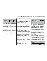
»Channel 1 Curve« (page 90)
–25%
m
OU
T
P
U
T
--
+
1
100
+73%
–25%
1
Point
Input
Curve
on
Output
Channel 1 C U R V E
In this option you can place one or more reference
points on the control curve of the throttle / brake ser-
vo in such a way that it responds to commands in ex-
actly the way you wish.
A good example of this is adjusting the airbrake “dead
zone”. Usually the brakes only extend from the wing
after the airbrake stick has been moved some dis-
tance, i. e. there is a “dead zone” in the airbrake stick
travel. “Bending” the curve slightly will shorten the
“dead zone”. The airbrakes will then extend from the
wing rather earlier, and you will have fi ner control over
the remainder of the travel. Similar arguments could
also be applied to the motor control system, which
could be controlled via C1 as an alternative.
If you are using a PCM, SPCM or APCM receiver, then
you should certainly move to the following menu …
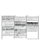
»Fail Safe settings« (pages 146 … 149)
Pos
hold
1
2
3
4
5
6
7
8
STO
F A I L S A F E
… and defi ne the receiver’s behaviour if interference
should occur, because “doing nothing” is the worst
thing you can possibly do – especially if you are set-
ting up a fi xed-wing model aircraft.
By default the transmitter is set to “Hold” mode, and
this means that the receiver continues to pass to the
servos the last control signals which it recognised
as valid, i. e. it simply “holds” things as they were. In
the most favourable case the power model continu-
es fl ying in a straight line for an indefi nite period, and
“lands” somewhere or other, without causing or suf-
fering major damage. However, if that should happen
in the “wrong” place and time, then the model could,
for example, end up tearing uncontrollably across the
fl ying site, endangering pilots and spectators alike.
That is why it is important to consider at this early sta-
ge whether it might not be better at least to set “Motor
off” as the Fail-Safe response, in order to avoid this
kind of risk.
In the case of an electric glider, on the other hand,
the Fail-Safe setting “Motor off” can also be used as
a means of stopping the motor and its propeller reli-
ably once the model has landed – all you have to do
is switch the transmitter off immediately after the lan-
ding.
Incidentally, the author defi nitely prefers a “braked
conclusion” to a fl ight in his own sight when the alter-
native is to watch the model drift off “somewhere or
other”.
Note:
For PCM20, SPCM20 and APCM24 mode, please
see the program descriptions on pages 146 … 149
for details of setting up the Fail-Safe system.
164
Programming examples: Fixed-wing model
Summary of Contents for mx-24s
Page 1: ...1...
Page 19: ...19 For your notes...
Page 35: ...35 For your notes...
Page 41: ...41 41 For your notes...
Page 57: ...57 For your notes...
Page 63: ...63 63 For your notes...
Page 69: ...69 69 For your notes...
Page 85: ...85 85 For your notes...
Page 99: ...99 For your notes...
Page 143: ...143 For your notes...
Page 191: ...191 For your notes...
Page 212: ...212 212 For your notes...
Page 213: ...213 213 For your notes...
Page 214: ...214 For your notes...
Page 216: ...216...


