background image

35 / 48

S1042_sh_V1

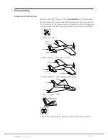
"2AILE"

For models with 2 aileron servos.
By aileron actuation the servos connected to the outputs 2 and 5 

work in parallel. The aileron trim acts on both servos.

Note

A conversion of "CH5" has in this case no effect.

"DELTA"

For delta and flying-wing model with one servo each wing.
The aileron and elevator control are carried out through the servos 

connected to the channels 2 and 3. The mixer for ailerons and ele-

vator are actuated by the transmitter. The aileron and elevator trim 

acts on both servos.

"V-TAIL"

For models with V-tail and 1 or 2 aileron servo.
The elevator and rudder are controlled by two separately-articulated 

rudders arranged in a V-shape connected to channel 3 and 4. The 

mixer for rudder and elevator is actuated by the transmitter. The 

rudder and elevator trim acts on both servos.
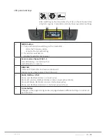
The related active setting will be indicated after the transmitter 

switch-on for about five seconds through the LED field on the trans-

mitter.

Programming step-by-step

1. 

Switch on the transmitter without programming connector.

These options can be selected in each of the three operating 

modes (NORMAL, TEACHER, PUPIL).

2.  Press the arrow button to the right of the LED field for at least 2 

seconds. 
After releasing, a short beep will be heard and the CH1 LED in the 

"REVERSE" LED line flashes.

3.  Press the arrow button to the right of the LED field until the LED 

of the desired option flashes.
Between the seven possible setting options CH1 ... CH5, 2AILE 

and DELTA is changed in the rotary process.
(The LEDs of options CH1 ... CH5 flash red, the LEDs of options 

2AILE and DELTA are green.)

4.  To change the status of the desired option push the MODE but-

ton. 
The blinking LED lights solid on.

5.  Use the arrow button to the right of the LED field to move to the 

next option and change the next option.

6.  You can always interrupt exit this menu by pushing for at least 2 

seconds the arrow button. 

Summary of Contents for MZ-10 HOTT

Page 1: ...mz 10 EN C o p y r i g h t G r a u p n e r S J G m b H Manual 6channel2 4GHztransmitter mz 10HoTT No S1042 No S1042 77...

Page 2: ...2 48 S1042_sh_V1...

Page 3: ...Adjusting the length of the control sticks 14 Opening closing the transmitter housing 14 Neutralizing the control sticks 16 Brake spring and ratchet 16 Control sticks centering force 16 Transmitter po...

Page 4: ...System menu Control mode 32 Servo direction and model type 34 Fail Safe 36 Teacher Student T S 40 Switch functions 42 Firmware update 44 Transmitter software update 44 SIMPLIFIED DECLARATION OF CONFO...

Page 5: ...and to ensure safe operation you must read and follow this user manual and all the safety notes before using the product and you have to respect those notes also for future use Note This manual is par...

Page 6: ...operation Such conditions may differ from state to state but this must be followed in every case Note Read through this entire manual before you attempt to install or use the transmitter Target group...

Page 7: ...ge 10 55 C Antenna Integrated Operating voltage 3 4 6 V Power consumption ca 130 mA Charging socket only for rechargeable batteries optionally available Dimensions ca 184 x 259 x 96 mm Weight approx 6...

Page 8: ...sons including children with reduced physical sensory or mental capabilities or lack of experience or knowledge or not capable to use safely the transmitter must not use the trans mitter without super...

Page 9: ...During transport protect the model and the transmitter from dam ages For your safety by handling the batteries CAUTION Protect the batteries from dust moisture heath and vibra tions Only use in dry lo...

Page 10: ...Eyelet for neck strap 3 D R switch switch function between 70 and 100 servo travel of the control functions 2 3 and 4 4 TRAINER switch see use mode 5 Right hand control stick 6 ARROW button 7 Trim 8...

Page 11: ...more infor mation mz 10 7 5 1 2 3 4 6 8 9 7 10 11 12 13 14 1 antenna integrated in the case 2 Eyelet for neck strap 3 Switch between Attitude and Rate mode 4 FLIP OFF LED 5 Right hand control stick 6...

Page 12: ...over 3 Data socket to connect a programming connector an optional SMART BOX a Bluetooth module an interface adapter to update the transmitter 4 Charging socket CAUTION The charge port is intended to c...

Page 13: ...n find more information about the listed accessories on www graupner de Digital trim with an acoustic feedback The two control sticks have digital trimming Briefly touch the trim ming switch to move t...

Page 14: ...force CAUTION Never switch the transmitter on while the housing is open Risk of short circuit Risk of fire Remove the batteries or the recharge able battery pack before opening the transmitter case Op...

Page 15: ...bles are properly placed 2 Screw the housing screws in their original position 3 Reconnect the battery box 1 2 2 3 3 4 3 4 3 1 Transmitter antenna integrated in the handle 2 Adjust screws for brake sp...

Page 16: ...spring and ratchet The outboard screw of the two marked in the figure adjust the brak ing force The inboard screw adjusts the strength of the ratchet for the respec tive control stick Note The right c...

Page 17: ...tep 1 Locate the battery case in the back of the transmitter 2 Slide the battery case cover 3 Remove the cover 4 The battery box is fixed in the battery case through Velcro tape 5 Lift the lower side...

Page 18: ...r automatic chargers recognize the battery charge In order to prevent damage to the protection switch and to the other components charging current should never exceed 1 A Receiver power supply If not...

Page 19: ...e symbols suitable for the particular model type are represented for example the coper symbol for the copter mod els of the transmitter mz 10 HoTT Note Firmware updates of the transmitter are carried...

Page 20: ...ng short power on melody Transmitter switched on Further solid on No melody Region setting GENERAL blinks each second No melody Country setting FRANCE on or blinks 1 beep each second Receiver battery...

Page 21: ...inding transmitter and receiver 2 Servo reverse channel CH 1 5 red LED blinking normal direction red LED solid on reverse 3 BIND LED indicates if transmitter and receiver are bound lights only by acti...

Page 22: ...Cut off operated with left upper switch Red LED blinks Motors OFF function is on Red LED off Motors OFF function is off 3 Rate operated with right upper switch Red LED lights Rate mode is on Red LED...

Page 23: ...n program mode Fail safe The buzzer beeps each 2 seconds and contemporary the sta tus LED blinks The country setting even if changed to FRANCE will be set to GENERAL so as the position of the digital...

Page 24: ...s SET button for approx 3 seconds to turn the receiver GR 12L to bind it to the bind mode The red LED turns off 3 Push the MODE button on the already switched on the mz 10 HoTT transmitter If the red...

Page 25: ...mitter output power decreases significantly then you can perform a function test in a distance not higher than 100 m After the 90 second range test the transmitter switches back to full output and the...

Page 26: ...odel or push simultaneously the left MODE and the right arrow keys for about 1 2 seconds to stop the test As soon as the range test has finished the model should react to the controls movements If thi...

Page 27: ...model should be interrupted immediately and the transmitter should be checked Eventually the transmitter s under voltage or receiver s temperature warning are active Then the battery should be charged...

Page 28: ...well as V tail and flying wing delta models with two aileron elevator servos can be controlled NO mixer active 1 central aileron servo for both wings Elevator Rudder Mixer 2AILE two aileron servos El...

Page 29: ...eron Left rudder elevator Right aileron or telemetry or special function Free or receiver power supply Receiver power supply Aerobrakes or motor servo or electronic speed controller L No S1012 Delta f...

Page 30: ...reversed Change servo 2 3 direction The elevator is correct and the aileron is reversed Change servo 2 3 direction and switch them in the receiver The aileron is correct and the elevator is reversed S...

Page 31: ...so many times as necessary to follow the rotary menu and reach up for the desired menu option As soon as you have reached the desired mode push and hold for approx 3 seconds the MODE button The actual...

Page 32: ...left elevator elevator rudder rudder full throttle idle aileron aileron full throttle idle rudder rudder elevator elevator aileron aileron elevator elevator aileron aileron full throttle idle rudder r...

Page 33: ...fore 2 Push the left MODE button so many times as necessary to follow the rotary menu and reach up for the desired control mode set ting Pay attention to the number of the beeps 3x beep red LED on MOD...

Page 34: ...dicator lights for about 5 seconds after exiting the selec tion menu so as every transmitter switching on Note Through the available optional SMART BOX the servo can be indi vidually adapted to the mo...

Page 35: ...ill be indicated after the transmitter switch on for about five seconds through the LED field on the trans mitter Programming step by step 1 Switch on the transmitter without programming connector The...

Page 36: ...owered on and until there is no valid sig nal from the transmitter take the positions saved in the receiver Completelyindependentlyfromreceiversettings hold or pos in case of interference HOLD In case...

Page 37: ...in the NORMAL position Push and hold the MODE button on the left of the LED panel while switching on the transmitter Release the button after having switched the transmit ter on and power the receive...

Page 38: ...correct control signal is received by the receiver Programming step by step 1 Select the desired mode 2 Press the MODE button for three to four seconds After releasing the button the status LED and t...

Page 39: ...to the position preset for this event all other channels remain in hold Programming step by step 1 Move the throttle stick and its trim to the desired position 2 Press the MODE button to the left of t...

Page 40: ...smitter The model provided for training must therefore be completely controllable by the teacher transmitter To conclude preparations bind the training model to the pupil trans mitter From a mz 10 HoT...

Page 41: ...ess the distance between the two transmit ters should not be too small up to 2m However always keep a suf ficient distance from the HoTT receiver already bound to the pupil transmitter In case of too...

Page 42: ...the reason WARNING The teacher transmitter should never be switched off during the use Without teacher transmitter the model cannot be controlled In case that during the control by the pupil transmit...

Page 43: ...osition Aerobatic mode that allows rolls and loopings Not suitable for beginners Switch for additional functions LED Moving the 3 way switch to the bottom you turn the copter light ning on OFF middle...

Page 44: ...re_Upgrade_gr_Studio Please follow the notes of the software The further procedure is also described in detail in the manual contained in the data package You can also download these from the download...

Page 45: ...Found target device The data transfer to the transmitter begins During the update on the transmitter the LEDs light on CH2 CH3 BIND and 2AILE The end of the data transfer will be indicated by the upda...

Page 46: ...ECLARATION OF CONFORMITY Graupner SJ hereby declares that the S1042 mz 10 HoTT complies with the Directive 2014 53 EU The full text of the EU Declaration of Conformity is available at the following In...

Page 47: ...isture Clean the product only with a dry cloth do not use detergent lightly rub Warranty Graupner SJ GmbH Henriettenstrassee 96 73230 Kirchheim Teck grants from the date of purchase of this product fo...

Page 48: ......

Reviews: