background image

 S1001.G1 and S1001.G1.77-USA-V1.0 

9 / 33 


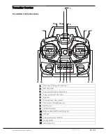
Transmitter Overview 


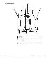
Transmitter Control Functions 


1


Antenna with folding and swivel joint


2


Neck strap eyelet


3


2 way switch (Attitude / Rate mode)


4


3 way switch (FLIP / OFF / LED)


5


Right stick


6


Arrow key (select video channel)


7


Trims (active in Attitude mode only)


8


On/off switch


9


LED indicators panel


10


MODE key (BIND; PHOTO (Snap); Range test)


11


Left stick


12


2-way switch (motor ON/OFF)


13


Carrying handle


14


Central status LED


10 

11 

12

13

14

mz-10 

Summary of Contents for mz-10c

Page 1: ...MANUAL mz 10c HoTT2 4GHztransmitterforcoptersanddrones No S1001 G1andS1001 G1 77 mz 10 ...

Page 2: ...Functions 9 Digital Trim 10 Adjusting Stick Length 10 Antenna Alignment 10 Attaching Neck Strap 10 Transmitter Back Side 11 Data Port 12 Charging Port 12 Transmitter First Time Use 13 Power Supply 13 Installing the Batteries 13 Using Rechargeable Batteries Option 14 Transmitter Functions 14 Transmitter Status Indications 14 LED Panel and Buttons 15 Multirotor Installation 16 Before Flight Safety C...

Page 3: ...21 Operation and Settings 22 Transmitter Programming 22 Country Setting 22 Stick Mode 23 Changing the stick mode 23 Fail Safe 24 Fail Safe Variant Selection 24 FAIL SAFE Mode 24 HOLD Mode 25 OFF Mode 26 STANDARD Mode 26 Switch Functions 27 Motor ON OFF Function 27 Attitude Rate Mode Switching 27 Switch for Additional Functions 27 Firmware Update 29 Transmitter Software Update 29 Declaration of Con...

Page 4: ...y need to bind the radio to the flight controller The mz 10C is compatible with all of Graupner Alpha multirotor products like the Alpha 250 Hornet 250 Alpha 110 and many others and will require a simple bind to fly any of these models One radio can fly all of these copters and you can expand your copter fleet by simply installing your own the GR 18C flight controller on any copter such as the Ver...

Page 5: ...ransmitter Graupner continuously enhances its products and reserves the right to change its products technology and equipment at any time and without prior notice Target Group This product is not a toy It is not suitable for children under 14 years old The operation of this product must be performed by experienced modelers If you do not have sufficient knowledge about operating radio controlled mo...

Page 6: ... 4 Temperature range 14 F to 131 F 10 C to 55 C Antenna Dipole Operating voltage 3 4 to 6V Power consumption approx 130mA Charging socket For rechargeable batteries only not included Dimensions approx 7 24 x 10 19 x 3 77 in Weight approx 22 2 oz Note Technical information and data for the receiver optional can be found in the receiver s user s manual This manual is included in the receiver s packa...

Page 7: ...egulations before using this remote control model These laws and regulations must be observed in for the safety of yourself and others and may vary by state region or country First time users carefully familiarize yourselves with this model s functions and commands Always exercise caution and operate this model responsibly To avoid risk of suffocation keep packaging materials away from babies and ...

Page 8: ... to protect from damages and excessive vibration Battery Safety CAUTION Protect batteries from dust moisture heat and vibrations For use in dry locations only Do not use damaged batteries Batteries should not be heated burned or short circuited Batteries not handled properly may catch fire explode or cause irritation and burns Damaged or corroded batteries may leak an electrolyte that is caustic a...

Page 9: ...t 3 2 way switch Attitude Rate mode 4 3 way switch FLIP OFF LED 5 Right stick 6 Arrow key select video channel 7 Trims active in Attitude mode only 8 On off switch 9 LED indicators panel 10 MODE key BIND PHOTO Snap Range test 11 Left stick 12 2 way switch motor ON OFF 13 Carrying handle 14 Central status LED 1 2 3 4 5 6 7 7 8 9 10 11 12 13 14 mz 10 ...

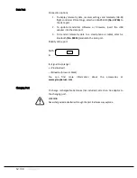
Page 10: ...tched back on Adjusting Stick Length To adjust the length of the stick hold the bottom half of the grip and loosen the connection by unscrewing the top half Lengthen or shorten the control stick by turning it up or down To tighten hold the bottom half of the grip and screw the two halves back together Antenna Alignment The antenna can be turned up to 90 Never point the antenna tip directly at the ...

Page 11: ...ansmitter Back Side 1 Case screws 2 Battery case cover 3 Data ports to connect USB connector for updates regional settings and control modes optional SMART BOX Bluetoothmodule 4 AC adapter port for rechargeable batteries not included 1 2 3 4 1 ...

Page 12: ...e data port 3 To transmit telemetry data to a smartphone or tablet attach a Bluetooth No S8351 moduleto the data port Polarity of the port DATA S S Signal line orange Plusline red Minusline brownorblack You can find more information about the accessories at www graupnerusa com Charging Port To charge rechargeable batteries not included attach an AC adaptor to the charging port WARNING Neverchargea...

Page 13: ...step by step 1 Locate the battery compartment in the back of the transmitter Slide the case cover down until it is disengaged 2 Remove the cover 3 The battery box is fixed in the compartment with Velcro tape Lift the lower side of the battery carefully 4 Gently pull the connecting plug to loosen the battery box wires 5 Remove the used batteries from the battery box 6 Insert new AA batteries 7 Reco...

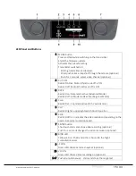
Page 14: ...Status Indications The transmitter is pre set at the factory to GENERAL Region Setting and Mode 2 After switching on the transmitter the central LED on top blinks red and an acoustic signal is emitted Refer to the chart below for status indication Central status LED Buzzer Description Solid on factory setting short power on melody Transmitter switched on Solid on No melody Country setting GENERAL ...

Page 15: ... on Rate mode active Advanced Mode Red LED off Attitude mode active Beginner Mode 4 CH6 Red LED on Flip mode active for 5 seconds only 5 CH7 Red LED lights upper right switch on LED position 6 CH8 Red LED off on indicates the video resolution depending on the used video system used optional 7 ENTER button Short push starts and stops video recording optional Push for 2 seconds changes the video res...

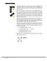
Page 16: ...front of the multirotor and the connector ports towards the back towards the ESC wires Wipe the surface of the multirotor with alcohol to assure proper adherence before attaching the GR 18C This step is critical to ensure that little to no vibration will affect the flight performance of the GR 18C receiver Secure the GR 18C with the supplied 3M VHB double sided tape Number the ESC connections to a...

Page 17: ...nd slow it down Users with little or no flying experience should consider having an experienced RC pilot assist during initial flights Move the throttle hold switch to the ARM position forward and advance the throttle slightly The propellers will start spinning Take note of the copter behavior If it starts rotating while close to the ground in an unanticipated manner check to see if the propellers...

Page 18: ...tches back to full power Range test step by step 1 Place the model in a safe location For copters make sure that the model is secured to a surface to avoid accidental takeoff 2 Turn on the transmitter 3 Check control response 4 Press the MODE and ENTER keys simultaneously The transmitter will start beeping 5 Move away from the model while activating the sticks An assistant may be useful to help wa...

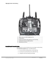
Page 19: ... not be opened except in the following cases To convert a self centering stick to non self centering To convert a non self centering stick to self centering To adjust the stick centering tension strength 1 Brake spring and ratchet adjusting screws 2 Centering lever 3 Screw to convert from self centering to non self centering 4 Stick self centering force adjusting screws 5 Brake spring and ratchet ...

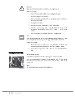
Page 20: ...d it to the bottom Note To avoid causing damage do not touch the electronic boards or the cables connecting the lower housing with the upper electronic components Closing step by step 1 Check if the upper and the lower part of the transmitter housing are correctly coupled and the tiny cables are properly placed 2 Screw the housing screws in their shrouds Reconnect the battery box Centering the Con...

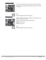
Page 21: ...ratchet for the respective control stick Note The right stick gimbal is specular to the left one Stick Centering Force The sticks centering force can also be adjusted The adjustment screw is located next to the return springs Adjust the spring force by turning the adjusting screw Right turn harder return Left turn softer return Note The right stick gimbal is specular to the left one ...

Page 22: ...the transmitter Connect the programming connector in the DATA S port on back side of the transmitter 2 Switch on the transmitter 3 Push the left MODE button on the front side of the transmitter to proceed to the desired menu option 4 Pay attention to the number of the beeps Disregard the FRANCE mode setting this is for backwards compatibility purposes only 5 Press and hold the MODE button for appr...

Page 23: ...to advance to the right programming option 4 Pay attention to the number of the beeps Buzzer Central status LED Description 3x beeps Solid on MODE 1 4x beeps Solid on MODE 2 5x beeps Solid on MODE 3 6x beeps Solid on MODE 4 5 Press and hold the MODE button for approx 3 seconds The new settings are automatically stored in the transmitter After the button is released a confirmation melody will sound...

Page 24: ...on after having switched the transmitter on and power the receiver previously bound to the transmitter The transmitter BIND LED should then light on yellow The transmitter is in Fail Safe mode The different Fail Safe modes HOLD ON OFF and STANDARD can be reached by briefly pressing the MODE button on the left of the LED panel Press to cycle between the following four options Active Mode Status LED...

Page 25: ...e to the desired position HOLD Mode In case of transmission interruptions all functions programmed to HOLD default to the last saved position To save this selection press and hold the MODE button for 3 4 seconds Release the button The status LED and the acoustic signal should indicate the transmitter power on status The transmitter is now in STICK MODE If not repeat the process until the mode is c...

Page 26: ...ly the throttle pitch CH1 moves to the position preset all other channels remain in HOLD position Switch to the Attitude mode and move the throttle stick and its trim to the desired position Press and hold the MODE button for 3 4 seconds to save the selection Release the button The status LED and the acoustic signal should indicate the transmitter power on status The transmitter is now in STICK MO...

Page 27: ...ment The stick movement acts directly proportionally to Roll and Nick After releasing the sticks the copter automatically moves back to the centering position Rate Mode Advanced Mode The stick movement determinates the rate without limiting angle movement and without automatically returning to the centering position This is an aerobatic mode that allows rolls and flips not suitable for beginners S...

Page 28: ...28 33 ...

Page 29: ...n can also be found at www graupnerusa com Scroll to the Support Links section at the bottom of the page and click on Downloads Use the dropdown option in the Radios Receivers section to find the appropriate version Before each update check the transmitter battery charge status Do not disconnect the link to the computer during an update Make sure that the link between the transmitter and computer ...

Page 30: ...few LEDs light are on 6 The end of the data transfer will be indicated by the update program The transmitter indicates the end of the transfer trhough the power on melody 7 Switch off the transmitter and remove the USB connection from the PC Your mz 10C is now updated with the latest software ...

Page 31: ...er SJ declares that the product is conform to EU norms FCC ID SNL 36204210 FCC ID SNL 16006100 CL 20961 36204210 CL 20961 16006100 EMV 2004 108 EC EN 301 489 1 V1 9 2 EN 301 489 17 V2 1 1 EN 62479 2010 LVD 2006 95 EC EN 60950 1 A11 A1 A12 A2 2013 R TTE 1999 5 EC EN 300 328 V1 8 1 EN 62311 2008 ...

Page 32: ...LLC at 3941 Park Drive Suite 20 571 El Dorado Hills CA 95762 warranties this product from the date of purchase for a period of 24 months The warranty applies only to the material or operational defects already existing when you purchased the item Damage due to wear overloading incorrect accessories or improper handling are excluded from the warranty The legal rights and claims are not affected by ...

Page 33: ...S1001 G1 and S1001 G1 77 USA V1 0 33 33 Notes ...

Reviews: