MIXER
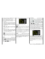
Up to five mixers can be programmed. In the "MIXER"
line, select one of mixers 1 … 5.
The following settings in this display
only
relate to the
mixers selected in the "MIXER" line.
Notice
If you have already programmed mixer functions
in the "Wing Mix" or "Free mixers" menus of the
transmitter, pay special attention to ensure that
these mixers do not overlap with those in the "RX FREE
MIXER menu!
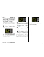
MASTER CH
("from")
According to the same principles described in the
section "
General information on programmable mix-
ers
", the signal at MASTER CH (signal source or
source channel) can be mixed with the SLAVE CH
(target channel) to the adjustable amount.
Select “00” if you do not require the mixer.
SLAVE CH
("to")
The signal of the MASTER CH (signal source or source
channel) is proportionately mixed with the SLAVE CH
(target channel). The level of mixing is determined
by the percentages entered in the "TRAVEL–" and
"" lines.
Select “00” if you do not require the mixer.
TRAVEL–/+
(level of mixing in %)
With the settings of these two lines, the percentage of
mixing is specified in relation to the MASTER signal
separately for both directions.
If the rudder travel is not as desired, observe these
Notices
.
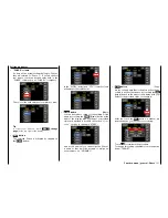
RX CURVE
With the RX CURVE function, you can administer con-
trol characteristics for up to three servos:
Value
Explanation
Possible set-
tings
Vx.xx
Firmware version
of the receiver
None
CURVE 1, 2
or 3 CH
Channel assig-
nment of the
respective curve
setting
1 … depending
on the receiver
TYPE
Curve type
A, B, C
see figure
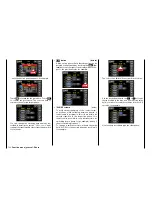
RX WING MIXER TAIL TYPE
(tail type)
Notice
The following model types are also available in
the base menu of a model and should preferably
be preset there. In this case,
always
leave the
TAIL TYPE at NORMAL.
If you still want to use the mixers integrated in the re-
ceiver, you can then select the preset mixer functions
for the corresponding model type:
• NORMAL
This setting corresponds to the classic airplane
type with a rear tail and separate rudder and ele-
vator. No mixing function is required for this mod-
el type.
• V-TAIL
With this model type, the control functions of the
elevator and rudder are linked to each other so that
each of the two tail flaps assumes the elevator and
rudder function controlled by a separate servo.
The servos are normally connected to the receiv-
er as follows:
OUTPUT CH 3: V-tail servo, left
OUTPUT CH 4: V-tail servo, right
If the rudder travel is not as desired, observe the
instructions on page
33
.
• ELEVON (delta/flying wing models)
The servos connected to outputs 2 and 3 assume
an aileron and elevator function. The servos are
normally connected to the receiver as follows:
OUTPUT CH 2: Aileron/elevator, left
OUTPUT CH 3: Aileron/elevator, right
107
Base menu - Telemetry | SETTINGS/DISPLAYS
Summary of Contents for mz-24 PRO
Page 13: ...13 Personal notes...
Page 19: ...19 Personal notes...
Page 37: ...37 Personal notes...
Page 59: ...Touch 59 Base menu Model selection...
Page 79: ...79 Personal notes...
Page 89: ...89 Personal notes...
Page 115: ...115 Personal notes...
Page 153: ...Helicopter model function menus Common function menus 153 Personal notes...
Page 169: ...169 Personal notes...
Page 187: ...187 Personal notes...
Page 199: ...199 Personal notes...
Page 207: ...Fixed wing model function menus System menus 207 Personal notes...
Page 211: ...211 Personal notes...
Page 219: ...219 Personal notes...
Page 237: ...237 Personal notes...
Page 238: ...238 Personal notes...
Page 239: ...239 Personal notes...


