To start the gas motor, make sure that the
THR.Limit
is
closed; that is, the carburetor can only be adjusted by
trimming its idle position. For this, observe punctually
the
Safety notes
at the end of this section. If the throt-
tle is set too high when the transmitter is turned on,
the RF module remains off and a visual and acoustic
warning are generated.
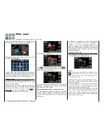
The following three diagrams show typical 3-point
throttle curves for different phases such as hover-
ing, aerobatics and 3-D flight.
Example throttle curves for different phases:
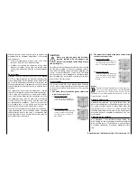
Notices
• In any case, you should use the
Throttle lim-
it function
(see the section "
CTL Set
"). The
throttle servo is normally completely separate
from the throttle curve at the left stop of the
(throttle limit) proportional dial DV1, the motor
is idling and only reacts to CH1 trimming. This
option allows you to start the motor from any
phase and turn it off using digital trimming.
After starting the motor, slowly turn the throttle
limiter to the opposite stop in order to com-
pletely actuate the throttle servo using the
throttle/pitch control stick. To keep the throttle
servo from being limited by the throttle limiter
in the full throttle direction, in line "CH12" of
the sub-menu "D/R,Exp", set the control trav-
el on the plus side of the "Travel" column the
value according to each phase to +125 %:
• Since electric drives do not require an idle
setting, when making the basic settings for
an electric helicopter, ensure that the control
range of the throttle limiter reliably exceeds or
falls below the setting range of the motor con-
trol unit which normally extends from -100%
to +100%.
The "Travel" setting of the throttle limiter may
have to be correspondingly adapted in all
phases in the line "CH 12" of the sub-menu
"D/R,Exp".
The throttle curve should be adapted in the
same manner as with a gas helicopter in flight.
Tip
In order to measure the flight time of a (gas) helicopter,
you can assign a control switch to the throttle limit servo
and use it to turn a
Timer
on and off.
Helicopters with
governor
In contrast to speed
controllers
that only regulate
performance like a carburetor,
governors
maintain a
constant speed in the system that they are monitoring
by independently regulating the provided output. In
the case of a gas helicopter, the control independently
controls the throttle servo like the motor control unit
of an electric helicopter.
Governors therefore only re-
quire a speed setting and not a classic throttle curve.
A deviation from the set speed occurs when the re-
quired output exceeds the maximum available output.
Normally, receiver output 8 is used for connecting a
governor
(see
Receiver assignation
). If this connection
is used, the gas throttle limiter is not used since it ex-
clusively acts via the "Throttle curve" mixer on output
6 which is not assigned.
In order to take advantage of the comfort and safety
features of the throttle limiter, connect the governor to
receiver output 6 in deviation from the general con-
necting strategy, and only adapt the throttle curve so
that it can assume the task of the normal servo.
161
Function menu | Helicopter model - Throttle curve
Summary of Contents for mz-24 PRO
Page 13: ...13 Personal notes...
Page 19: ...19 Personal notes...
Page 37: ...37 Personal notes...
Page 59: ...Touch 59 Base menu Model selection...
Page 79: ...79 Personal notes...
Page 89: ...89 Personal notes...
Page 115: ...115 Personal notes...
Page 153: ...Helicopter model function menus Common function menus 153 Personal notes...
Page 169: ...169 Personal notes...
Page 187: ...187 Personal notes...
Page 199: ...199 Personal notes...
Page 207: ...Fixed wing model function menus System menus 207 Personal notes...
Page 211: ...211 Personal notes...
Page 219: ...219 Personal notes...
Page 237: ...237 Personal notes...
Page 238: ...238 Personal notes...
Page 239: ...239 Personal notes...


