Butterfly
Adjusting the braking system of gliders
This sub-menu is displayed, according to the selected
model type and its configuration.
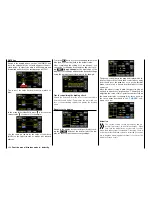
In the basic transmitter display, use your finger or the
provided stylus to touch the gear icon labeled "F":
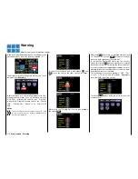
Touch
The display switches to the blue function menu. Touch
the menu item "
Butterfly
".
Touch
Depending on the selected number of ailerons and
flaps, the display shows different views: The top of the
two following figures shows an example of the display
when setting the minimum "2AILE", and the bottom
figure shows the display when selecting the maximum
"... 4FLAP".
In this menu, you can set a special flap arrangement,
the
crow
position or
butterfly
. In this braking posi-
tion, both
ailerons are moved slightly upward
, and the
flaps move downward as far as possible
. By means
of an additional mixer (the "elevator curve" mixer de-
scribed below), the elevator is trimmed so that the
flight speed does not change significantly in com-
parison to the normal flight position. Otherwise, there
is a danger that the model will slow down too much
and, after the brake system is retracted (for example
to lengthen a landing approach that is too short), will
crash or fall.
This interaction of the flaps, aileron and elevator con-
trol the gliding angle when approaching a landing.
(The butterfly flap position is frequently used in sports
models instead of brake flaps or spoilers).
Phase-dependent settings
The here mentioned sub-menu offers the possibility
of phase specific settings. Recognizable on the top
left side of the display in green color is displayed the
phase name. As standard is displayed the name of the
phase 1, which is indicated by the name "NORMAL"
or "PHASE 1". As soon as you will have defined one
or many other phases in the "
PHASE
" menu, you will
be able to switch among those phases. Activate the
corresponding switch or switches if desired to switch
between the phases.
Programming
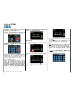
The butterfly mixers described below are actuated by
the throttle/brake control stick assigned by default to
the "CH1" input, or alternately by any other transmit-
ter control element that is assigned to the "CH1" input
of the "
CTL Set
" sub-menu .
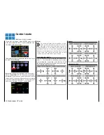
In most cases, however, the selection is limited to
preset control, and the airbrake is operated using the
non-neutralizing CH1 control stick:
The use of other control elements offers also the pos-
sibility to be able to control the airbrakes alternatively
also through another accessory function control, in
case the CH1 control stick is going to be used for oth-
er scope.
202
Function menu | Airplane models - butterfly
Summary of Contents for mz-24 PRO
Page 13: ...13 Personal notes...
Page 19: ...19 Personal notes...
Page 37: ...37 Personal notes...
Page 59: ...Touch 59 Base menu Model selection...
Page 79: ...79 Personal notes...
Page 89: ...89 Personal notes...
Page 115: ...115 Personal notes...
Page 153: ...Helicopter model function menus Common function menus 153 Personal notes...
Page 169: ...169 Personal notes...
Page 187: ...187 Personal notes...
Page 199: ...199 Personal notes...
Page 207: ...Fixed wing model function menus System menus 207 Personal notes...
Page 211: ...211 Personal notes...
Page 219: ...219 Personal notes...
Page 237: ...237 Personal notes...
Page 238: ...238 Personal notes...
Page 239: ...239 Personal notes...


