background image

Gyro  System

 SRVS G490T


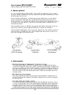
SRVS gyro system, Order No. 5137 


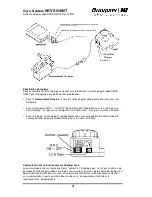
channel used for adjusting gyro gain; the area around the centre of its travel is used for this. 

In the simplest case a slider or rotary control is employed on the transmitter, providing control 

over the full range of this channel (100% - 0 – 100%). If this transmitter control is moved in 

the one direction from centre, gyro gain increases in "normal" mode; if it is moved in the other 

direction from centre, gyro gain increases in "heading lock" mode. 


Since it is not normally necessary or sensible to switch between normal and heading lock 

modes, wherever possible you should completely suppress the mode you do not wish to use, 

and expand the adjustment range of gyro gain over the full travel of the transmitter control; 

this is very simple to achieve, especially with sophisticated computer radio control systems 

such as the mc-22, mx-22 and mc-24. Simply reduce the effect of the transmitter control to 

about 40% and offset the centre by 60% in the appropriate direction; if necessary the 

direction of effect of the transmitter control can then be reversed so that it works in the way 

you wish. 

In heading lock mode all mixers which affect the tail rotor must be switched off. Since the two 

operational modes "normal" and "heading lock" require very different support in terms of 

transmitter mixers, you should only ever switch modes by switching flight phases, so that 

these requirements are taken into account automatically. However, a degree of instability is 

inevitable when you switch between normal and heading lock mode, and this means that it is 

essential to carry out a "hard" (sudden) switch between flight phases, i.e. without any time 

delay. To date only the mc-24’s latest software solves this problem completely, as it is ca-

pable of switching individual channels "abruptly" when a "soft" flight phase switch is carried 

out. 


Note: when the model is on the ground, the neutral position of the servo in "heading lock" 

mode may differ from the neutral position in "normal" mode. You may also find that the servo 

does not return to centre in this situation after giving a control command. This is completely 

normal and only ever occurs on the ground - never in flight. 


Typical programming procedure with the mc-24 and PROFI-ROM: 

The required end-result is (typically) two flight phases: Phase 1 ("Acro") in "normal" mode, and 

Phase 2 ("Acro 3-D") in "heading lock" mode. 

• 

Assign the flight phase switch and phase names as described in the mc-24 manual. 

• 

In the "Transmitter control setup" menu for control 7 (gyro gain and normal / heading-lock 

switch) assign slider 7 for both flight phases. 

• 

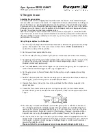
"Transmitter control setup" menu for input 7: 

Flight phase "Acro": 

Travel "SYM" to +40% Offset to +60%  

Flight phase "Acro 3-D": 

Travel "SYM" to -40% Offset to -60%  

• 

In the "Non-delayed channels" menu set channel 7 to "no delay". 

• 

For the "Acro " phase all the mixers in the "Heli mixers" menu which affect the tail rotor - roll -

> tail rotor, pitch-axis -> tail rotor, Ch1 -> tail rotor - can be used normally. 

• 

For the "Acro 3-D" phase switch off all the mixers in the "Heli mixers" menu which affect the 

tail rotor: roll -> tail rotor, pitch-axis -> tail rotor, Ch1 -> tail rotor (in this case set all curve 

points to "0" to produce a horizontal line). 

• 

Be sure to use the phase trims to store the tail rotor trim in both phases – don’t use the 

global trim memory.  


Summary of Contents for SRVS 5137

Page 1: ...it anderen als den vorgesehenen JR Servos und son stigen JR Fernsteuerungskomponenten verwenden andernfalls besteht Brand Verletzungs und Ausfallgefahr Unbedingt die Steuerrichtung des Gyro Systems be...

Page 2: ...n beachten 3 Eigenschaften Heading Lock Betriebsart Das Gyro System SRVS G490T besitzt neben der normalen Betriebsart in der eine Dre hung um die stabilisierte Achse lediglich ged mpft wird die Betrie...

Page 3: ...ung vom Sender aus Die Wirkungseinstellung und umschaltung vom Sender her ist in das Sensorgeh use des Gyro Systems eingebaut Dadurch ist eine sehr genaue lineare und reproduzierbare Ein stellung der...

Page 4: ...Digital und Superservos Nor f r Standardservos Mit dem Einstellregler Limit Gain wird der Servoausschlag an die Mechanik der Heckrotor steuerung angepasst Servoausschlag bei Begrenzereinsatz Umschalt...

Page 5: ...leich bleibt generell ausgeschaltet 5 Mischer f r die Ausblendung des Gyro Systems in Abh ngigkeit von der Heckrotorsteuerung Gyro Control Kreiselausblendung unbedingt deaktivieren 6 Kreiselsystem in...

Page 6: ...er rechts bewegt Ungef hr ab Halbausschlag muss das Servo auf den Begrenzer auflaufen also bei weiterer Kn ppelbewegung in Richtung Voll ausschlag stehen bleiben Erfolgt der Begrenzereinsatz bei unter...

Page 7: ...lugphasen kombiniert werden Die auftretende Insta bilit t der Heckrotorsteuerung im Bereich des Wechsels zwischen Normal und Heading Lock Modus macht es allerdings erforderlich einen entsprechenden Fl...

Page 8: ...enigstens 3 Sekunden lang nicht zu ber hren Wenn Sie das Modell w hrend dieser Zeit bewegen kann eine falsche Trimmeinstellung entstehen In diesem Fall Empf nger ausschalten dann wieder einschalten We...

Page 9: ...tated JR servos and other JR radio control system components or you run the risk of fire injury and system failure Always check the direction of operation of the gyro system If you set the gyro to cou...

Page 10: ...ion to the yaw axis by installing additional gyro systems Please refer to the diagrams below which indi cate the correct orientation for the gyro system in the model 3 Characteristics of the SRVS G490...

Page 11: ...e gain and direction of effect can be set from the transmitter and this feature is built into the electronic circuitry of the gyro system This means that it is easy for the pilot to adjust the system...

Page 12: ...normal for standard servos The adjustor marked Limit Gain is used to adjust the servo travel to suit the tail rotor control mechanism servo travel at limiter trigger point Switching to Heading Lock m...

Page 13: ...ansmitter features a dynamic torque compensation mixer it must be disabled switched off permanently 5 Be sure to disable the mixer which suppresses the effect of the gyro system in response to a tail...

Page 14: ...at different stick positions on both sides you can correct this using the servo centre adjustment on the transmitter adjust this function until the limiter works symmetrically on both sides Now fit th...

Page 15: ...heading lock mode and this means that it is essential to carry out a hard sudden switch between flight phases i e without any time delay To date only the mc 24 s latest software solves this problem co...

Page 16: ...you shift the model by mistake switch off the receiver then switch it on again When the helicopter is standing motionless on the ground you will sometimes hear a hum ming sound from the tail rotor se...

Page 17: ...ec d autres servos que les servos JR pr vus et utilisez uniquement les quipements R C JR autrement il existe un danger d incendie de blessure ou de panne V rifiez absolument le sens de commande du sys...

Page 18: ...sur les diff rents axes 3 Particularit s Mode de fonctionnement Heading Lock Conservateur de cap Le syst me de gyroscope SRVS G490T comprend en plus du mode de fonctionnement normal pour simplement am...

Page 19: ...r Le r glage de l effet et la commutation partir de l metteur sont int gr s ici dans le bo tier du palpeur du syst me du gyroscope Il en r sulte une possibilit de r glage tr s pr cise li n aire et rep...

Page 20: ...un servo digital et un Super servo Nor pour un servo standard Avec le r glage Limite de gain le d battement du servo sera adapt la commande m canique du rotor de queue D battements du servo avec limit...

Page 21: ...mut 5 D sactiver absolument le mixeur pour l annulation du syst me de gyroscope en d pendance de la commande du rotor de queue Gyro Control Annulation gyroscope 6 Placer le gyroscope dans le mode de f...

Page 22: ...fi en d pla ant le manche de commande lentement du milieu vers la gauche ou la droite aux environs de la moiti du d battement le servo doit stopper sur le limiteur et rester arr t m me avec d autres m...

Page 23: ...commutation des modes de fonctionnement devra aussi tre combin e avec une commuta tion des phases de vol L instabilit qui se produit dans la commande du rotor de queue au niveau de l change entre les...

Page 24: ...ndant au moins 3 secondes Si le mod le est d plac durant ce temps il peut en r sulter un faux r glage de trim Dans ce cas couper le r ception puis la remettre en contact Lorsque l h licopt re reste im...

Reviews: