GB-18
2. Remove the spacer, handle, and eccentric spacer from the
steering lever.
NOTE: Position the right and left handles at the same height
position.
3. Install the spacer, handle, and eccentric spacer in the
appropriate height position. Do not tighten the nut holding
the eccentric spacer.
4. Turn the eccentric spacer until the right and left handles are
the same height. Tighten nut.
ADJUSTING THE PARKING BRAKE
The parking brake might need adjustment over time and after
new brake paddles have been installed.
Check Adjustment
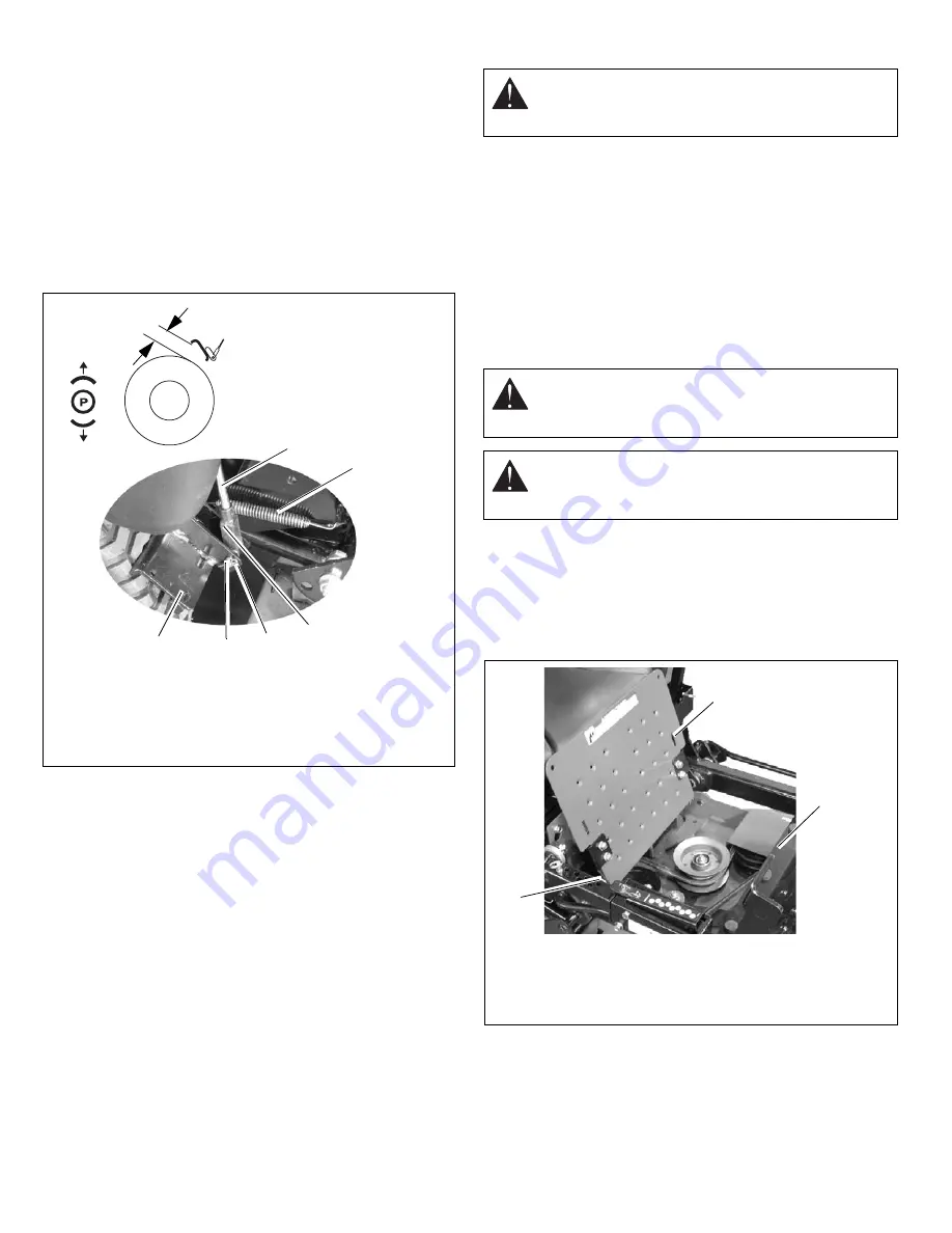
NOTE: Be sure to check the parking brake on both sides of the
unit (Figure 14).
1. Disengage parking brake.
2. Measure the distance between the bottom edge of the
brake paddle and the tire.
There should be 3/8 in. - 1/2 in. (9.5 - 15.9 mm) between
brake paddle and tire.
3. Tires - Adjust tire pressure for front tires; 20-25 PSI
(138-172 kPa), rear tires; (992056, 314) 12-15 PSI (83-103
kPa), (992065) 15-18 PSI (103-124 kPa).
Adjust the Parking Brake
1. Disengage the parking brake.
2. Disconnect return springs from frame.
3. Disconnect clevis from parking brake paddle.
4. Turn clevis up the brake rod to decrease distance or down
the brake rod to increase the distance between the brake
paddle and the tire.
5. Replace clevis on parking brake paddle.
6. Replace return springs.
7. Check adjustment and repeat as needed.
PTO BELT
PTO Belt Access
1. Properly stop and park unit (See Operation on page 10).
2. Lower the mower.
3. Place seat in most rearward position.
4. Remove belt covers.
5. Place foot board in open position (Figure 15).
1. Parking Brake
Paddle
2. Brake Rod
3. Clevis
4. Return Springs
5. Hair Pin
6. Clevis Pin
Figure 14
OF3303
3/8 in. - 1/2 in.
(9.5 - 15.9 mm)
1
2
3
4
5
6
CAUTION: Use care when releasing spring tension.
Keep body parts well away from springs when
performing this operation.
WARNING: MOVING PARTS can cut or amputate
body parts. ALWAYS wait for moving parts to stop
before performing maintenance or service.
CAUTION: DAMAGED OR WORN BELTS may result
in injury and/or damage to unit. Check belts for
excessive wear or cracks often.
3
1. Footboard in
open position
2. Support Frame
3. Pivot
Figure 15
1
2
Summary of Contents for Promaster 34Z
Page 24: ...GB 24 ...


