
795-92155
01/23/14
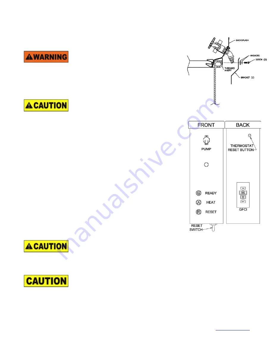
Graymills Corporation – 3705 N. Lincoln Ave. / Chicago, IL 60613 – Phone: 773.477.4100 Fax: 773.477.8673 –
3
MACHINE INSTALLATION AND OPERATION
1. Place unit on a smooth, level surface in a well ventilated area.
2. Install backsplash as show to the right (BIO536R only).
3. Read all warnings posted on machine.
4. Inspect electrical control box, cord and plug for wear or damage.
Do not use machine or add fluid if any wear or damage is noticed until impaired
components are repaired or replaced.
5. Install filter cartridge:
a. Unscrew filter cartridge bowl.
b. Remove clear plastic packaging from new filter cartridge and remove
BIO-POUCH from hollow center of cartridge.
c.
Install new filter cartridge in the cartridge bowl.
d. Re-attach filter cartridge bowl to filter body.
Be sure electrical cord is unplugged and cleaning solution and heater coil is cool
before adding cleaning solution or performing any maintenance.
6. Remove center sink drain (stainless steel strainer basket, mesh strainer assembly).
7. Add 30-gallons of Super Biotene
TM
solution to the base reservoir tank.
8. Add one (1) BIO-POUCH of microbes to tank, found inside filter cartridge.
9. Put center sink drain assembly back into sink drain opening.
10. Plug power cord into properly grounded 115V, 15 amp circuit. Full load amp-draw of unit
is 12 amps.
11. Press TEST button on GFCI on rear of control (right) to ensure switch is operating
properly. Press RESET button on GFCI to prepare unit for operation.
12. Air pump will begin operation immediately upon power being applied to the machine and
the red “RESET” light will illuminate.
13. Toggle RESET switch located under the electrical box to begin operation. If the unit has
an adequate level of cleaning solution in the tank, the green “READY” light will illuminate
and the red “RESET” light will extinguish.
14. The amber “HEAT” light indicates power to the heater.
15. If cleaning solution is not at the appropriate temperature and heat is required you should
hear the thermostat engage with a “CLICK” and the amber “HEAT” light will illuminate.
Should this not happen, press the red thermostat reset button on the rear of the control
box (right). Should this problem persist: unplug machine and call factory.
16. When the unit reaches its predetermined temperature, the “HEAT” light will extinguish,
indicating the cleaning solution is at the proper temperature to obtain maximum cleaning
efficiency. For maximum cleaning efficiency, allow heater to warm solution for 2 to 4
hours before use.
17. To operate the fluid pump, toggle PUMP switch on front of electrical box to the “ON”
position.
18. For fluid via the flexible hose turn the directional valve counterclockwise to the left.
19. For fluid via the flow-thru brush turn the directional valve clockwise to the right.
When not in use return flow-thru brush to brush clip holder to holder to avoid obstructing lid closure (BIO436R only).
20.
Failure to keep proper liquid level will result in burning out the pump and heater coil, creating a potential fire hazard.
To
prevent this, this unit is equipped with a low liquid level device which will shut off the pump and heater. If solution stops circulating
and the red “RESET” light becomes illuminated, immediately turn off and unplug unit. Follow steps 6 through 9 above for
instructions on refilling unit.
21.
When finished, turn pump off and close lid to minimize liquid loss due to evaporation (BIO436R only).
Do NOT unplug the machine for extended periods of time. The internal air pump and heaters are necessary for effective
bioremediation. This will cause the microbes to go dormant and will adversely affect the bioremediation process. If microbes do
not reactivate after operating temperature has been reached, a new BIO-POUCH should be added.
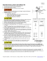
Backsplash Assembly for BIO536R-A
Operator Interface
BIO436R-A and BIO536R-A
Front and Back


