background image

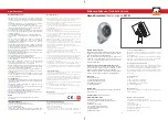
The Remote Control Model is equipped with a multi-directional radio transmitter . This feature will enable you to guide the pool cleaner directly to areas of the pool 
requiring additional cleaning attention or for quick clean-ups. When you press the Right or Left Buttons, the unit will turn until the button is released. Then, the machine will 
proceed straight ahead in the new direction. Pressing the Forward/Reverse button will cause the cleaner to proceed in the new direction after the button has been 
released.


The Remote Control has an advanced cleaning program with two options:

 Standard Mode-cleans the bottom of the pool only in just 1 hour (maximum 90 minutes on large swimming pools).
 Super Mode-cleans the bottom and walls of the swimming pool in just 3 hours. Every remote control unit is shipped from the factory with the 

Standard Mode as the primary program. To Switch from the Standard to the Special Mode, simply press the "Program" button once. The machine will immediately receive 
the command and will start to clean the bottom and the walls. Your signal that the machine is in the special mode is that the machine will 

climb up to the waterline in the first contact with a wall.  To return to the Standard Mode, simply press the “Program” button again only when the machine is 

on the pool bottom. 

 When the Power Supply is turned off, the Mode is automatically returned to the "Standard" (floor cleaning only) Mode.

Cleaning Modes

Option 1

:

Option 2

:

PLEASE NOTE:

stop for a moment after pressing 

the button and


important

Please be sure to always keep your pool cleaner properly stored anywhere between 10 to 40 degrees Celsius (50 to 104 degrees 
Fahrenheit). This will keep the motors, plastics and seals protected. Failure to comply will result in loss of warranty.

Wireless Remote Control - R/C Model 

Using Radio Remote Control Feature 
and accessing Cleaning Modes

REPLACING 
THE BATTERY
1. 

 Remove the 

top screw (Fig. 
1).

2.

  Pull the top of 

the cover away 
from the 
transmitter and 
then pull 
upwards (Fig. 2)

3.

  Replace the battery and make sure 

the polarity is the same as the existing 
battery (Fig. 3)

4.

  Push the cover downwards into the 2 

slots :Fig. 4)

5.

  Push the top of the cover towards the 

battery until it snaps into place (Fig. 5)

6.

  Put the screw back into place.  

4

Summary of Contents for Evolution AR208201

Page 1: ......

Page 2: ...end of its cleaning cycle This will allow the motors to cool adequately Do not leave the cleaner in the pool all the time Always remember to turn the power supply OFF and unplug it from the power outl...

Page 3: ...fig 2a 2b Place the unit in the water Turn the unit side to side in the water to allow air to escape from the body and then let the cleaner sink to the bottom of the pool fig 3 Then spread the cable...

Page 4: ...transformer socket Fig D 3 Push the plug into the socket of the transformer all the way in 4 Once the plug is in rotate the plug to the right to lock it into place Fig E 5 To remove the plug first ro...

Page 5: ...n the bottom and the walls Your signal that the machine is in the special mode is that the machine will climb up to the waterline in the first contact with a wall To return to the Standard Mode simply...

Page 6: ...m lid assembly in the body Push down on it until lock tabs will snap into place properly Maintenance and adjustment Shut off and unplug the power supply every time you remove the cleaner from the wate...

Page 7: ...b With side plate detached take out the wheel tube from the machine c Open the end hub and pull out the worn PVA brush see fig 6 d Place the new PVA brush on to the hexagonal tube and close it with th...

Page 8: ...es Allow 45 seconds between ON and OFF d Check for and remove any debris such as hair string or leaves that may be obstructing the free movement of the Drive Pulley 5 Drive Belts 6 or Drive Tracks 7 e...

Page 9: ...r unit The Flaps should move freely to open and close Clean and free the Valve Flaps 23 if necessary 3 Unit does not move but does pump water 4 Unit does not pick up dirt and debris 5 Unit does not se...

Page 10: ...th the RC System 25 call your service center for assistance Place the Robot on the ground and unplug the cable from the transformer With one hand holding the E Z Swivel walk away from the Robot pullin...

Page 11: ...aque cycle de nettoyage Ceci permettrait aux moteurs de se refroidir ad quatement Ne laissez pas le nettoyeur en permanence dans la piscine N oubliez pas de mettre l interrupteur en position off arr t...

Page 12: ...Balancer l appareil d un c t l autre afin de permettre l air de s en chapper puis laisser l appareil descendre au fond de la piscine D ployer ensuite le c ble sur la surface de la piscine d une mani r...

Page 13: ...he d abord d bloquer la en tournant vers la gauche et en suite tirer l ext rieur Fig F a Le voyant lumineux indique que la machine est en marche b Le bouton Vert met la machine en position ON marche c...

Page 14: ...ce que le bouton soit rel ch Ensuite la machine va proc der tout droit dans la nouvelle direction En appuyant sur le bouton avant arri re le nettoyeur proc dera dans la nouvelle direction une fois qu...

Page 15: ...uyez sur le support et l assemblage se remettra en place automatiquement Eteignez et d branchez le transformateur avant de sortir I appareil de I eau Nettoyez le filtre apr s chaque cycle de nettoyage...

Page 16: ...ehors d placer Ia nouvelle brosse PVA sur Ie tube h xagonale et la bloquer l aide du moyeu terminal e remettre en tat Ia roue d entra nement et remonter la flasque avec les quatre vis moyeu brosse en...

Page 17: ...eux tapes d Enlevez les d bris possibles tels que des feuilles des cheveux ou des fibres qui pourraient obstruer la bonne marche des courroies d entra nement ou des chenilles e Contr lez que les courr...

Page 18: ...librement Ils doivent s ouvrir et se fermer sans entrave Les d coincer au besoin 3 Le robot ne bouge pas mais la pompe aspire 4 Le robot ne prend pas la salet et les d bris 5 Le robot ne semble pas co...

Page 19: ...b Utilisez le pivot E Z comme d montr ci dessous 8 Le c ble flotteur est vrill Entretien du c ble Le c ble peut s entortiller apres un certain temps d utilisation Afin de le d lacer simplement bloquez...

Page 20: ...tzschalter versorgt werden der eine festgelegte Fehlerstromansprechgrenze von nicht mehr als 30 mA aufweist Die Verbindung zu der Abzweigleitung muss den geltenden lokalen und nationalen Regeln f r Ve...

Reviews: