background image

Section 2: Operating Instructions

NTS2507, NTS2509, & NTS2511 s/n+ 2019+ NTS Seeder 313-900M

7/1/19

26

Table of Contents

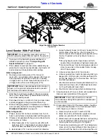
Level Seeder With Pull Hitch

1.

Transport to the field with seeder attached. For 
detailed instructions, see 

“Transporting with 

Seeder Attached” 

on page 24.

2.

Park seeder on level ground, raise seeder fully up, 
place tractor in park or set park brake, shut tractor off, 
and remove switch key before dismounting.

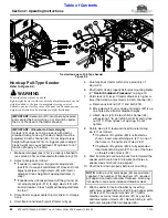
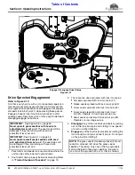
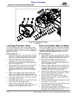
Refer to Figure 2-8:

3.

Remove wire retaining pins (#10), transport 
locks (#11), and stroke control spacers (#9) from all 
three hydraulic lift cylinders and store on nearby 
storage racks as shown. Secure transport locks to 
storage racks with wire retaining pins (#10).

4.

Start tractor and lower seeder to the ground using 
factory float. Keep tractor hydraulic lever in factory 
float while seeding seeds.

5.

Pull ahead 15 feet or until both front and rear rollers 
are fully engaged in the ground and then stop.

6.

Without changing height of implement, shut tractor 
down properly before dismounting. Refer to 

“Tractor 

Shutdown Procedure” 

on page 19.

Refer to Figure 2-8:

7.

Place a level (#19) on the mainframe from front to 
back to verify frame is level (parallel) with the ground. 

8.

If frame is not parallel with the ground, unhook tractor 
from seeder as follows:

a. Attach park jack (#14) to jack mount (#16) with 

detent pin (#13). Insert detent pin horizontally as 
shown. Make sure detent pin is fully inserted.

b. Extend jack (#14) to remove load from drawbar.

IMPORTANT: 

Front angling spike rollers will not 

function properly unless frame is level to the ground.

IMPORTANT: 

Always operate seeder with transport 

wheels on the ground and seeder level to prevent 
dirt build-up and seeder damage.

c. Leave hydraulic hoses (not shown) hooked to the 

tractor unless they are too short to move the 
tractor forward 6" with seeder unhooked from the 
tractor. If needed, unhook hydraulic hoses as 
follows:

Move hydraulic control lever back and forth 
several times to release all hydraulic pressure.

Disconnect hoses from tractor duplex outlet and 
store loose ends on the seeder frame to keep 
dirt off the couplers.

d. Unhook safety chain (#12) from tractor. 

e. Unhook seeder from tractor by removing hitch pin 

keeper (#5), hitch pin (#6), and flat washers (#1A 
& #1B). Be careful not to lose washers, hitch pin, 
and hitch pin keeper.

f. Start tractor and drive forward until drawbar (#1) is 

removed from clevis (#2). If attached, be careful 
not to pull hydraulic hoses tight.

g. Shut tractor down properly before dismounting.

9.

Adjust park jack (#14) up or down until seeder main 
frame is level (parallel) with the ground.

10. Check clevis hitch (#2). The clevis plates should be 

in line with the drawbar. If not, then readjust clevis 
hitch height up or down as follows:

a. Remove nylock nut (#17) and bolt (#18). 

b. Move clevis (#2) until clevises upper and lower 

plates are parallel with tractor drawbar.

c. Attach clevis (#2) to seeder hitch (#4) with existing 

1"-8 x 6" GR5 bolt (#18) and nylock nut (#17). 
Draw nylock nut up snug. Do not tighten.

d. To protect wire retaining pin (#7) from being bent, 

move pin to the hole furtherest from the clevis or 
store pin with the tractor until unhooking the unit.

IMPORTANT: 

Clevis (#2) should be in line with 

tractor drawbar during field operation to reduce wear 
on the drawbar.

Align Clevis With Tractor Drawbar

Figure 2-8

39057

Summary of Contents for NTS2507

Page 1: ...bsequent instructions and warnings are serious follow without exception Your life and the lives of others depend on it Illustrations may show optional equipment not supplied with standard unit XXXXX Base Unit with Options Base Unit 39464 39465 313 900M Operator s Manual NTS2507 NTS2509 NTS2511 s n D1250L 2019 NTS Seeder Copyright 2019 Printed 7 01 19 ...

Page 2: ...or your machine Update the record by adding the machine weight and measurements provided in the Specifications Capacities Section of this manual with the Option s weight and measurements Dealer Contact Information Model Number Serial Number Machine Height Machine Length Machine Width Machine Weight Delivery Date First Operation Accessories Name Street City State Telephone Email 7 1 19 NTS2507 NTS2...

Page 3: ...actor Shutdown Procedure 19 Hook up 3 Point Seeder 20 Check LED Lights 21 Check Tractor Clearance 21 Unhook 3 Point Seeder 21 Hook up Pull Type Seeder 22 Store Park Jack on Seeder Frame 23 Unhook Pull Type Seeder 23 Install Transport Locks Spacers 24 Transporting with Seeder Attached 24 Level Seeder With 3 Point Mount 25 Level Seeder With Pull Hitch 26 Filling Small Seeds Seedbox 27 Filling Grass ...

Page 4: ...r Roller Center Bearings 63 Small Seed Drive Sprocket Bearing 63 Native Seed Drive Sprocket Bearings 63 Seed Cup Drive Shafts 64 All Seeds Drive Sprocket 64 Roller Chains 64 Seed Cup Sprockets Nylon Washers 65 Gearbox for the Native Seedbox 65 Axle Hub Bearing 65 Section 9 Specifications Capacities 66 Section 10 Features Benefits 68 Section 11 Troubleshooting 69 Section 12 Torque Values Tire Infla...

Page 5: ...hildren to play on the power machine or implement Use extra caution when backing up Before the tractor starts to move look down and behind to make sure the area is clear Safety at All Times Careful operation is you best assurance against an accident All operators no matter how much experience they may have should carefully read this manual and other related manuals or have the manuals read to them...

Page 6: ...quipped with brakes Avoid contact with any over head utility lines or electrically charged conductors Always drive with load on end of loader arms low to the ground Always drive straight up and down steep inclines with heavy end of a tractor with loader attachment on the uphill side Engage park brake when stopped on an incline Maximum transport speed for an attached equipment is 20 mph DO NOT EXCE...

Page 7: ...r hearing loss Wear suitable hearing protection such as earmuffs or earplugs Operating equipment safely requires the operator s full attention Avoid wearing headphones while operating equipment Use Seat Belt and ROPS Great Plains recommends the use of a CAB or roll over protective structures ROPS and seat belt in almost all power machines Combination of a CAB or ROPS and seat belt will reduce the ...

Page 8: ...ograms offered by the employer Be aware of and use optional equipment controls such as water sprays local exhaust ventilation and enclosed cabs with positive pressure air conditioning if the machine has such equipment Otherwise respirators shall be worn Where respirators are required wear a respirator approved for protection against crystalline silica containing dust Do not alter respirator in any...

Page 9: ...Important Safety Information 7 1 19 5 This page left blank intentionally ...

Page 10: ... nearest dealer visit our dealer locator at www greatplainsmfg com 3 Some new equipment installed during repair requires safety labels to be affixed to the replaced component as specified by Great Plains When ordering new components make sure the correct safety labels are included in the request 4 Refer to this section for proper label placement To install new labels a Clean surface area where lab...

Page 11: ...ble of Contents 39009 Tow Option 39012 Tow Option 39012 818 339C WARNING High Pressure Fluid Hazard 3 Places On all hydraulic lift cylinders 818 337C WARNING Excessive Speed Hazard 1 Place On 3 point hitch frame 818 398C CAUTION Falling hazard standing stepping on tires 2 Places On both rear axle arms ...

Page 12: ...g hazard walking on walk board 2 Places At each end of walk board Tow Option 39982 Tow Option 39012 39012 39011 818 254C DANGER Rotating Roller Hazard 2 Places On rear roller scraper 2 Places On front spike rollers 858 816C NOTICE Attach to tractors hydraulics with Float Capabilities only 2 Places End of hydraulic hoses with quick couplers ...

Page 13: ... 39748 With Native Seedbox 39467 39091 39055 838 614C 2 x 9 Red Reflector 2 Places Back left rear right rear of seedbox 818 543C DANGER Guard Missing Beneath Guard 2 Places Behind chain guards 858 765C WARNING Pinch Point Hazard 2 Places Both sides of Spike Roller adjustment lever 838 615C 2 x 9 Amber Reflector 2 Places Front side of main frame ...

Page 14: ...ders have the capabilities to seed different grasses Legumes small seeds and other food plot mixes See Seed Rate Charts on pages 38 45 52 for a detailed list of seeds each seedbox is designed for seeding The NTS Series Seeders are ideal for renovating pastures grassy medians grassy parkings reclaiming right of ways and seeding food plots See Specifications Capacities on page 66 and Features Benefi...

Page 15: ...and transporting a fully loaded seeder Use Land Pride s QH20 Quick Hitch or one that is compatible Torque Requirements Refer to TorqueValues Chart for Common Bolt Sizes on page 70 to determine correct torque values when tightening hardware See AdditionalTorque Values at bottom of chart for exceptions to common torque values Dealer Preparations This NTS Seeder has been mostly assembled at the facto...

Page 16: ... to the sling brackets will bend the brackets and can damage the seedbox Reference Figure 1 3 Always use a spreader bar to keep lift chains vertical while lifting the seeder off the ground IMPORTANT Sling brackets on the native seedbox and small seeds seedbox are used only when lifting the seedbox unattached from the seeder Do not lift the NTS Seeder with these sling brackets Improper Lifting Meth...

Page 17: ...djustment lever 1 is at 0 and some of the cup sleeves 7 are against sprocket washers 6 but not all then adjust those cups that are not as follows a Loosen hex nuts 8 and move seed cups 9 away from seed sprockets 5 until they stop b Tighten 1 4 20 hex nuts 8 to the correct torque for GR5 bolts 10 Adjust Left Hand Small Seeds Seedbox 1 Refer to Figure 1 4 Move seed rate adjustment lever 1 to 100 and...

Page 18: ...he seeder IMPORTANT Do not adjust park jack 11 to raise spike rollers off the ground Acremeter Option Refer to Figure 1 8 on page 15 1 Remove upper guard 26 as follows a Remove bolt 15 lock washer 21 flat washer 20 hand knobs 25 and guard 26 b Set guard 26 and attaching hardware 15 20 21 25 aside for reuse later 2 Remove lower guard 6 as follows a Remove bolts 15 flat washers 21 and guard 6 b Set ...

Page 19: ...ghest surface on snap on actuator 9 and tighten nuts 17 to the correct torque 13 Attach console 1 to the seedbox side panel with 8 32 x 1 round head screws 13 flat washers 23 lock washer 22 and hex nuts 17 Tighten hex nuts to the correct torque 14 Install roller chain 27 to drive sprocket 4 and all seeds drive sprocket 5 15 Adjust idler sprocket 2 to adjust chain take up and tighten nut 18 to the ...

Page 20: ... Make sure couplings 4 are attached to hydraulic lift cylinders 1 3 Re phasing Deck Lift Cylinders and Plumbing Figure 1 9 Refer to Figure 1 9 1 Re phasing hydraulic cylinder 3 50 x 6 x 1 25 TIE 2 Re phasing hydraulic cylinder 3 25 x 6 x 1 25 TIE 3 Re phasing hydraulic cylinder 3 00 x 6 x 1 25 TIE 4 Quick disconnect poppet type coupling 3 4 FORB male 5 Elbow 3 4 MJIC x 3 4 MORB 6 3 8 Hydraulic hos...

Page 21: ... seeder hydraulic hoses to the tractor duplex outlet with float capabilities 6 With tractor started engage hydraulics until hydraulic cylinder at the front of the seeder reaches full extension 7 Disengage hydraulics and wait one minute This will allow any trapped air to migrate toward the re phasing port 8 Repeat steps 6 7 for each of the two remaining hydraulic cylinders IMPORTANT Be sure tractor...

Page 22: ...Section 1 Assembly Set up NTS2507 NTS2509 NTS2511 s n D1250L 2019 NTS Seeder 313 900M 7 1 19 18 Table of Contents This page left blank intentionally ...

Page 23: ...ed See Section 4 Grass Seed Rate Adjustment 34 Set speed change sprocket Refer to Grass Seed High Low Range Set up 34 Adjust seed rate for Small Seed Refer to Section 5 Small Seed Rate Adjustment 44 Adjust seed rate for Native Seed Refer to Section 6 Native Seed Rate Adjustment 52 Read and follow all maintenance instructions Refer to Section 8 Maintenance Lubrication 55 Inspect seed cups and seed ...

Page 24: ...tch can be attached to the tractor to provide quick and easy 3 point hook up and detachment See your nearest Great Plains dealer to purchase a Quick Hitch NOTE Center clevis pin 3 and pin keeper 5 are customer supplied 6 Start tractor and slowly operate controls to raise and lower seeder to make sure the seeder clears the tractor tires frame and drawbar 7 If drawbar interferes with seeder shut tra...

Page 25: ...implement Check Tractor Clearance Refer to Figure 2 1 on page 20 1 Shut tractor down properly See Tractor Shutdown Procedure on page 19 2 Adjust front rollers all the way forward Refer to Front Spike Roller Angle on page 33 for detailed instructions 3 From the tractor seat slowly raise and lower seeder with hydraulic 3 point lift while watching for drawbar clearance tire clearance and 3 point clea...

Page 26: ...t can cause hydraulic lift cylinders to not function properly in the field 5 Carefully back tractor within close proximity of clevis 2 6 Shut tractor down properly before dismounting Refer to Tractor Shutdown Procedure on page 19 7 Hold clevis 2 level If tractor drawbar is higher or lower than clevis adjust clevis in hitch channel 4 a Remove nylock nut 17 and bolt 18 b Move clevis 2 up or down unt...

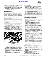
Page 27: ...s should be installed on all hydraulic lift cylinders If transport locks are not installed they should be installed before transporting the seeder Refer to Install Transport Locks Spacers on page 24 5 Check LED lights to verify they are operating correctly Refer to Check LED Lights on page 21 Unhook Pull Type Seeder Refer to Figure 2 4 on page 22 1 Clean seedboxes seed cups and drop tubes before u...

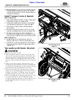
Page 28: ...der down until seeder is resting on transport locks 2 and stroke control spacers 4 Transporting with Seeder Attached WARNING To avoid serious injury or death When traveling on roadways travel in such a way that other vehicles may pass you safely Use LED lights clean reflectors and a slow moving vehicle sign that is visible from the back to warn operators in other vehicles of your presence Always c...

Page 29: ... way that faster moving vehicles may pass you safely 7 Reduce tractor ground speed when turning Leave enough clearance so the seeder does not contact obstacles such as buildings trees or fences 8 Shift tractor to a lower gear when traveling over rough or hilly terrain IMPORTANT The slow moving vehicle sign should not be used when transporting equipment on a truck or trailer exceeding speeds of 25 ...

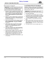
Page 30: ...l to the ground IMPORTANT Always operate seeder with transport wheels on the ground and seeder level to prevent dirt build up and seeder damage c Leave hydraulic hoses not shown hooked to the tractor unless they are too short to move the tractor forward 6 with seeder unhooked from the tractor If needed unhook hydraulic hoses as follows Move hydraulic control lever back and forth several times to r...

Page 31: ...r lid gently while keeping hands and fingers clear of pinch points 7 Lock lid down with lid latch handles 1 to keep moisture out Small Seeds Seed Rate Chart 39054 Seed Splash Plates Grass Seedbox Figure 2 10 Filling Grass Seedbox WARNING To avoid serious injury or death Always lower rear roller 3 and spike rollers to the ground with hydraulic float or 3 point before working around the seeder check...

Page 32: ...d remains constant as ground speed is varied The front rollers cultivates the soil crush clods press down small stones and forms a seedbed They can be angled from 0 degrees non aggressive to approximately 18 degrees very aggressive The condition of soil and type of vegetation will determine front roller angle Soil that has already been worked will not require as aggressive an angle as hard soil or...

Page 33: ...l seeds drive sprocket 1 has a patented lockout clutch with lockout pin 2 This clutch allows the operator to back up without damaging the seed cups and without disengaging any of the four drive sprockets See Drive Sprocket Engagement on page 30 for additional information regarding the four drive sprockets Main Drive Sprocket With Lockout Clutch Figure 2 12 39082 ...

Page 34: ...set on 0 IMPORTANT See Figure 5 1 on page 44 Never operate small seeds seedbox with seed rate adjustment lever set on 0 The seed cups will be damaged if they are turning with seed rate adjustment lever set on 0 3 There are five drive sprockets with lock in out pins All seeds sprocket with lock in out pin 1 Native seeds sprocket with lock in out pin 2 Grass seeds sprocket with lock in out pin 3 Gra...

Page 35: ...pipelines sprinkler heads and any unforeseen objects underground Mark any potential hazards 2 Clear area to be seeded of rocks branches and other foreign objects on top the ground Mark any potential hazards IMPORTANT Never make turns with any of the rollers in contact with the ground Always lift unit up off the ground when making turns IMPORTANT Attach seeder to a tractor before calibrating it for...

Page 36: ... seed drop area between the front and rear rollers The rear roller then presses seed into firm contact with the soil to promote a superbly high germination rate Seeding should not be attempted in wet or muddy conditions Now that you understand how it works it is time to begin seeding You may want to make a few passes with the All Seeds Drive System locked out just to make sure your front rollers a...

Page 37: ...hown In all other positions one bent pin is in back of the gang slide and the other is in front of the gang slide IMPORTANT Lock nuts 4 should allow gang slide 2 to move easily with minimum gap between lock nuts and gang slide Mud Scraper Adjustments Figure 3 2 Mud Scrapers Refer to TorqueValues Chart for Common Bolt Sizes on page 70 when tightening hardware Refer to Figure 3 2 Adjust Front Mud Sc...

Page 38: ...nut 6 Tighten nut to correct torque 8 Install driven chain 9 with 74 links 9 Adjust drive chain 9 with idler sprocket 12 When adjusted properly tighten 3 8 locknut 11 to the correct torque 10 Install drive chain 3 with 66 links 11 Adjust drive chain 3 with idler sprocket 2 When adjusted properly tighten 3 8 locknut 1 to the correct torque 39082 Low Range Sprocket and Chain Set up Figure 4 2 Low Ra...

Page 39: ... GR5 bolt 15 lock washer 16 and flat washer 17 Tighten bolt to 31 ft lbs Return to Standard High Low Range This drive arrangement bypasses the reduction drive and is good for seeding healthy grass plots This set up can be operated with high range or low range set up See Grass Seed High Low Range Set up on page 34 Refer to Figure 4 3 1 Remove 3 8 bolt 15 lock washer 16 and flat washer 17 Remove han...

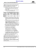
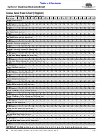
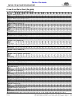
Page 40: ...g product Gate Handle Shown In Highest Position To Clean Out Seed Fully Open Gate By Rotating Gate Handle To This Position 39025 Grass Seed Rate Adjustment Lever Figure 4 5 Grass Seed Rate Adjustment 1 Use English charts on beginning page 38 and Metric charts on page 41 to help determine seeding rate a Decide which drive range is required low or high range If necessary change speed change sprocket...

Page 41: ...hen A x 1 lbs 1000 sq ft 1 20 hectare then A x 20 kgs hectare 100 sq meters then A x 100 kgs hectare 100 sq meters then A x 10 kgs 1000 sq m i If calculated grass seed rate is different than the suggested settings in the charts then increase or decrease the seed cup adjustment lever 4 Repeat calibration procedure if the results of the calibration vary greatly with the chart Model No No of Rear Rol...

Page 42: ...2 15 5 16 9 18 2 19 6 21 22 3 23 7 25 1 26 4 27 8 Low Range 0 6 1 1 5 1 9 2 3 2 8 3 2 3 6 4 1 4 5 4 9 5 4 5 8 6 2 6 6 7 1 7 5 7 9 8 4 8 8 Low Range w Reduction 0 11 0 18 0 28 0 35 0 42 0 52 0 59 0 66 0 75 0 83 0 90 0 99 1 07 1 14 1 21 1 31 1 38 1 45 1 55 1 62 High Range 77 151 224 297 372 444 517 592 664 737 812 884 957 1032 1104 1177 1252 1324 1397 1472 Low Range 24 48 71 94 118 141 164 187 211 2...

Page 43: ...11 8 12 7 13 6 14 5 15 5 16 4 17 3 18 2 Low Range 0 3 0 6 0 8 1 1 1 4 1 7 2 2 3 2 6 2 9 3 2 3 5 3 7 4 4 3 4 6 4 9 5 2 5 5 5 8 Low Range w Reduction 0 06 0 11 0 15 0 20 0 26 0 31 0 37 0 42 0 48 0 53 0 59 0 64 0 68 0 74 0 79 0 85 0 90 0 96 1 01 1 07 High Range 35 68 103 141 179 220 262 306 352 398 446 495 545 596 648 701 754 808 862 916 Low Range 18 28 41 55 71 89 107 127 147 168 189 210 231 252 271...

Page 44: ...65 6 73 4 80 9 87 7 96 1 107 4 112 9 124 5 137 2 High Range 1 12 1 37 2 14 4 38 6 88 9 16 11 52 13 96 16 51 19 51 22 06 25 09 27 92 30 86 33 92 37 19 40 74 44 52 44 81 45 37 Low Range 0 37 0 43 0 75 1 45 2 33 3 12 3 87 4 70 5 56 6 26 7 26 8 27 9 25 10 19 11 05 12 11 13 54 14 23 15 69 17 30 Low Range w Reduction 0 07 0 08 0 14 0 27 0 43 0 57 0 71 0 86 1 02 1 15 1 34 1 52 1 70 1 88 2 03 2 23 2 49 2 ...

Page 45: ...6 103 109 116 123 129 136 Low Range 3 5 7 9 11 14 16 18 20 22 24 26 28 30 32 35 37 39 41 43 Low Range w Reduction 0 6 0 9 1 3 1 7 2 0 2 6 2 9 3 3 3 7 4 0 4 4 4 8 5 2 5 5 5 9 6 4 6 8 7 2 7 5 7 9 High Range 86 169 251 332 416 497 578 662 743 825 908 989 1071 1155 1235 1317 1401 1481 1563 1647 Low Range 27 54 79 105 132 158 183 209 236 262 288 313 339 366 392 417 444 470 496 521 Low Range w Reduction...

Page 46: ... 30 35 40 44 49 53 58 62 66 71 76 80 84 89 Low Range 1 3 4 5 7 8 10 11 13 14 16 17 18 20 21 22 24 25 27 28 Low Range w Reduction 0 2 0 6 0 7 0 9 1 3 1 5 1 8 2 0 2 4 2 6 2 9 3 1 3 3 3 7 3 9 4 0 4 4 4 6 5 0 5 2 High Range 39 77 116 157 201 247 294 343 394 446 500 555 611 668 726 785 845 905 966 1027 Low Range 20 32 46 62 80 99 120 142 165 188 212 236 259 282 304 325 345 364 380 395 Low Range w Reduc...

Page 47: ...6 7 1 8 0 7 9 8 9 High Range 54 2 66 3 103 5 211 9 332 9 443 2 557 3 675 4 798 8 943 9 1067 3 1213 9 1350 8 1493 0 1641 0 1799 2 1971 0 2153 9 2167 9 2195 0 Low Range 17 9 20 8 36 3 70 2 112 7 150 9 187 2 227 4 269 0 302 9 351 2 400 1 447 5 493 0 534 6 585 9 655 1 688 4 759 1 837 0 Low Range w Reduction 3 3 3 8 6 7 12 9 20 7 27 8 34 5 41 8 49 5 55 7 64 6 73 6 82 3 90 7 98 4 107 8 120 5 126 7 139 7...

Page 48: ...sure an accurate seeding rate 4 Calibrate dispersal rate for your specific seed a Poor seed over the three seed cups at the outboard end of the seeder Do not allow any seed to reach the other cups b Pull seed tubes out of the three seed cup drops c Lower seeder frame onto support blocks that will support the rear roller just above ground level d Rotate rear roller to make sure drive system is work...

Page 49: ...Plus Pounds per 1000 Square Feet Low Range 0 1 0 1 0 1 0 2 0 2 0 3 0 3 0 4 0 5 0 5 0 6 0 6 0 7 0 8 0 8 0 9 0 9 1 0 1 1 1 1 Biologic New Zealand Full Draw Pounds per Acre Low Range 0 0 0 0 0 0 0 0 0 4 3 5 7 0 8 7 12 6 15 2 16 5 20 0 22 2 24 8 25 2 27 4 29 1 35 2 41 3 41 8 Biologic New Zealand Full Draw Pounds per 1000 Square Feet Low Range 0 0 0 0 0 0 0 0 0 0 0 1 0 2 0 2 0 3 0 3 0 4 0 5 0 5 0 6 0 6...

Page 50: ... 17 4 18 3 20 9 23 1 24 8 26 5 29 1 30 0 32 6 35 2 Imperial NO Plow Pounds per 1000 Square Feet Low Range 0 0 0 0 0 0 0 1 0 1 0 2 0 2 0 3 0 3 0 3 0 4 0 4 0 5 0 5 0 6 0 6 0 7 0 7 0 7 0 8 Imperial Whitetail Chicory Plus Pounds per Acre Low Range 0 4 0 4 3 5 6 1 8 7 10 0 12 6 15 2 18 3 20 9 23 9 27 0 29 6 31 3 33 9 37 0 40 0 42 2 45 2 48 3 Imperial Whitetail Chicory Plus Pounds per 1000 Square Feet L...

Page 51: ...7 8 9 4 11 2 13 0 14 8 16 3 18 1 19 6 21 6 23 5 24 9 26 7 28 4 32 3 37 4 Rye Pounds per 1000 Square Feet Low Range 0 0 0 0 0 1 0 1 0 1 0 2 0 2 0 3 0 3 0 3 0 4 0 4 0 4 0 5 0 5 0 6 0 6 0 6 0 7 0 9 Sweet Clover Pounds per Acre Low Range 0 0 1 7 3 8 5 8 7 9 9 9 12 6 14 6 16 9 18 9 21 1 23 0 24 9 27 1 29 3 31 4 33 4 35 6 37 5 39 5 Sweet Clover Pounds per 1000 Square Feet Low Range 0 0 0 0 0 1 0 1 0 2 0...

Page 52: ... 0 3 0 4 0 6 0 9 1 1 1 3 1 6 1 7 2 0 2 3 2 6 2 8 3 0 3 3 3 6 3 8 4 1 4 2 4 6 4 9 Low Range 0 0 2 1 4 4 6 8 9 5 12 2 14 7 17 4 19 8 22 5 25 2 27 9 30 7 33 4 36 3 39 1 41 8 44 3 47 0 49 7 Low Range 0 0 0 2 0 4 0 7 1 0 1 2 1 5 1 7 2 0 2 3 2 5 2 8 3 1 3 3 3 6 3 9 4 2 4 4 4 7 5 0 Low Range 0 0 0 0 0 4 3 4 3 4 6 8 6 8 9 8 10 8 14 1 15 1 18 0 20 5 22 9 23 9 27 3 28 2 30 3 33 6 34 6 Low Range 0 0 0 0 0 0 ...

Page 53: ... 4 2 7 3 0 3 3 3 7 4 0 4 1 4 5 5 1 5 1 5 4 Low Range 0 0 3 4 4 4 7 3 9 3 12 7 14 6 18 0 20 5 23 9 26 8 29 3 33 2 36 5 39 0 41 5 45 4 47 7 51 2 54 1 Low Range 0 0 0 3 0 4 0 7 0 9 1 3 1 5 1 8 2 1 2 4 2 7 2 9 3 3 3 7 3 9 4 1 4 5 4 8 5 1 5 4 Low Range 0 0 0 0 0 0 0 0 0 0 1 0 2 9 3 4 6 4 6 8 6 8 8 7 9 8 10 2 11 2 11 7 12 7 15 1 16 1 19 1 Low Range 0 0 0 0 0 0 0 0 0 0 0 1 0 3 0 3 0 6 0 7 0 7 0 9 1 0 1 0...

Page 54: ... 32 6 35 3 38 0 41 0 43 4 46 2 48 9 Low Range 0 0 0 0 0 3 0 4 0 8 1 0 1 3 1 6 1 9 2 2 2 4 2 7 3 0 3 3 3 5 3 8 4 1 4 3 4 6 4 9 Low Range 0 0 1 1 3 0 4 6 6 5 8 4 10 5 12 8 14 9 17 1 19 3 21 4 23 6 25 8 28 2 30 2 32 6 34 7 36 7 38 8 Low Range 0 0 0 1 0 3 0 5 0 7 0 8 1 1 1 3 1 5 1 7 1 9 2 1 2 4 2 6 2 8 3 0 3 3 3 5 3 7 3 9 Low Range 0 0 2 0 3 8 5 2 6 9 9 0 10 3 12 2 14 1 16 0 17 8 19 8 21 7 23 6 25 8 2...

Page 55: ...Section 5 Small Seed Rate Adjustment NTS2507 NTS2509 NTS2511 s n D1250L 2019 NTS Seeder 313 900M 7 1 19 51 Table of Contents This page left blank intentionally ...

Page 56: ...gearbox drive lever 7 to the selected drive number 5 by pulling up on lock pin 6 and adjusting lever to the correct number g Release lock pin 6 Make sure lock pin is fully down and lever 7 is locked from movement h Place removed sprocket 4 on the sprocket storage holder 12 Secure all four unused sprockets on the holder with linchpin 12 4 Refer to Figure 2 13 on page 30 Engage native seeds with loc...

Page 57: ... material to seed different proportions of seed types affecting density and ground preparation 4 To help insure an accurate seeding rate Great Plains recommends that you test and adjust your seeder per the seed rate calibration procedures provided on page 52 See Notes Below Drive Sprockets High Low Range Sprocket Gearbox Drive Number Setting 15 Teeth 19 Teeth 27 Teeth 33 Teeth Low Range 1 2 8 lbs ...

Page 58: ... Figure 7 3 Electronic Acremeter Option Refer to Figure 7 3 The Acremeter is programed to count rear roller shaft rotations and display it as acres or hectares This meter should be used only when seeding full width Refer to Electronic Acremeter Manual No 194 074M for detailed programming and operating instructions Slow Moving Vehicle Sign Accessory Refer to Figure 7 4 Great Plains offers as an acc...

Page 59: ...unction performance and life of the implement Replace parts only with genuine OEM parts Roller Chains Sprockets Refer to Figure 8 1 Figure 8 2 on page 56 Your drive system uses standard 40 roller chain and is designed for low maintenance General Chain Sprocket Maintenance 1 Inspect all chains and sprockets for wear and replace as needed 2 Clean and lubricate all roller chains with chain lubricant ...

Page 60: ... chain 14 If needed loosen 3 8 16 flange nut 15 and adjust sprocket 16 in or out to adjust chain take up Tighten nut 15 to the correct torque 2 Check chain 14 to ensure it is not over tightened Grass Seed Standard Drive Chains Refer to Figure 8 3 1 Check tension of chain 3 If needed loosen 3 8 16 hex flange nut 1 and adjust sprocket 2 to tighten loosen chain 3 39052 Grass Seed Standard Drive Figur...

Page 61: ... inspect chains for wear frequently Always replace worn roller chains when needed Small Seed Roller Chains Grass Seed Standard Roller Chains Refer to Figure 8 5 for high range set up and Figure 8 6 for low range set up Item Part No Description 1 809 307C CHAIN RL 40 X 40 PITCH W CON 2 809 060C CHAIN RL 40 X 66 PITCH W CON 3 809 091C CHAIN RL 40 X 8 PITCH W CON 4 809 060C CHAIN RL 40 X 66 PITCH W C...

Page 62: ...estigate and remove the cause Trash build up between spikes can prevent spikes from penetrating the soil properly Clean trash from spike rollers as needed Rear Packer Roller Refer to Figure 8 9 on page 59 The rear packer roller assembly should be free to float up and down to follow the field terrain The rear roller wheels 3 should turn freely If the assembly does not float or the wheels do not tur...

Page 63: ...freely repeat steps 2 7 above 9 Loosen 3 8 16 hex nuts 1 on all spike and plain roller clamps 2 10 Adjust roller wheels 3 and roller clamps 2 as follows NTS2507 a Slide all roller wheels 3 and roller clamps 2 towards the center of the rear packer roller assembly until all slack is removed NTS2509 a On the left hand rear packer roller assembly slide all roller wheels 3 and end roller clamps 2 towar...

Page 64: ...y to the right 100 to fully open fluted seed cups e Run seeder over the ground to power the fluted seed cups and to remove out of reach seeds f Check drop tubes to make sure they are not clogged with seeds Clean any drop tube that may have seeds plugged in them g Make a final sweep or vacuum of the fluted seed cups to finish the cleaning job h Seasonally rinse each seed cup thoroughly with water s...

Page 65: ...ls 8 Store seeder on a level hard surface in a clean dry place Inside storage will reduce maintenance and make for a longer seeder life 9 Follow all unhooking instructions Refer to Unhook Pull Type Seeder on page 23 Ordering Replacement Parts Great Plains offers equipment in factory standard green with black highlights Special attention must be given to the green part number The suffix number 81 m...

Page 66: ...rease Quantity 4 5 pumps 39018 39018 39416 25 Hours Rear Roller Left End Bearing 1 Zerk Type of Lubrication Multi purpose Grease Quantity 4 5 pumps Lubrication Points 50 Hrs Multi purpose spray lube Multi purpose grease lube Multi purpose oil lube Intervals in hours at which lubrication is required Lubrication Legend 25 Hours Rear Roller Right End Bearing 1 Zerk Type of Lubrication Multi purpose G...

Page 67: ...Type of Lubrication Multi purpose Grease Quantity 1 2 pumps 25 Hours 25 Hours Rear Roller Center Bearings NTS2509 NTS2511 only 2 Zerks In the middle on rear rollers Rotate each roller by hand until notch aligns with zerk Type of Lubrication Multi purpose Grease Quantity 4 5 pumps Native Seed Drive Sprocket Bearings 2 Zerks Type of Lubrication Multi purpose Grease Quantity 1 2 pumps every 25 hours ...

Page 68: ...of Lubrication Multi purpose Grease Quantity 4 5 pumps Roller Chains See Roller Chains Sprockets on page 55 Type of Lubrication Chain Lubricant Quantity Coat Generously 25 Hours Seed Cup Drive Shafts Reference Small seed and grass seed cup drive shaft Type of Lubrication Oil Quantity Squirt a generous amount of oil on to the square drive shafts Move seed rate adjustment levers back and forth to ge...

Page 69: ...k together IMPORTANT Use sparingly Excess sealant may squeeze off the intended surface and into the bearings and gears causing them to lock up As Required Seed Cup Sprockets Nylon Washers Type of Lubrication Graphite Powder Great Plains 821 042C 1 lb Container Quantity Mix as needed 1 teaspoon of powdered graphite for every bushel of seed in the seedbox IMPORTANT DO NOT use petroleum lubricant on ...

Page 70: ...ets Grass seedbox Small seeds seedbox Native seedbox Two on grass seedbox for lifting grass seedbox or complete NTS Seeder assembly Two on small seeds seedbox for lifting only the small seeds seedbox Two on native seedbox for lifting only the native seedbox Seedbox lids Heavy duty lid with seed splash guard Individual seedbox lockouts Spring loaded lock in out pins for each seedbox drive All seeds...

Page 71: ... NTS2511 138 3 4 352 cm 18 1 4 46 cm NTS2507 55 1 2 141 cm NTS2509 56 3 4 144 cm NTS2511 56 3 4 144 cm 3 4 2cm NTS2507 73 1 2 187 cm NTS2509 88 224 cm NTS2511 117 1 4 298 cm NTS2507 87 1 2 222 cm NTS2509 101 3 4 258 cm NTS2511 130 3 4 332 cm NTS2507 97 246 cm NTS2509 111 3 4 284 cm NTS2511 139 1 4 354 cm 47 110 cm 11 1 2 29 cm 132 1 4 336 cm NTS2507 69 3 4 177 cm NTS2509 71 180 cm NTS2511 71 180 c...

Page 72: ...reference Easy seed rate adjustment on grass and native seedbox Proper seed rate adjustment lever positioning is conveniently indicated on the seed rates chart for ease of setting and adjustment with a high level of confidence 40 Roller chain drive Provides for smooth and quiet running with a high degree of reliability Adjustable idlers and slotted take ups help keep the drive chains allow for cha...

Page 73: ...and is sticking to rollers Seed cup drive shaft not turning Spring loaded lock in out pin is not engaged Engage pin to start shaft turning Actual seeding rate is different than desired Seed treatment will affect seeding rate if the chemicals buildup in seed cup Unless cleaned regularly this buildup can cause breakage of the seed cup shaft Feed cup sprocket locked up or twisted feed cup drive shaft...

Page 74: ...0 260 485 355 3 4 16 260 190 405 295 570 420 M20 X 2 5 280 205 440 325 610 450 7 8 9 225 165 585 430 820 605 M20 X 1 5 310 230 650 480 900 665 7 8 14 250 185 640 475 905 670 M24 X 3 480 355 760 560 1050 780 1 8 340 250 875 645 1230 910 M24 X 2 525 390 830 610 1150 845 1 12 370 275 955 705 1350 995 M30 X 3 5 960 705 1510 1120 2100 1550 1 1 8 7 480 355 1080 795 1750 1290 M30 X 2 1060 785 1680 1240 2...

Page 75: ...ons or modifications failures caused by lack of normal maintenance as outlined in the operator s manual repairs made by non authorized personnel items replaced or repaired due to normal wear such as wear items and ground engaging components repeat repair due to improper diagnosis or repair by the dealer temporary repairs service calls and or mileage to and from customer location overtime premium o...

Page 76: ...Great Plains Mfg 1525 E North St P O Box 5060 Salina KS 67402 ...

Reviews: