Section 3: Roller Adjustments
NTS2507, NTS2509, & NTS2511 s/n+ 2019+ NTS Seeder 313-900M
7/1/19
33
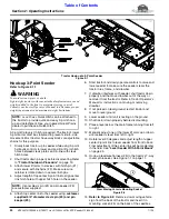
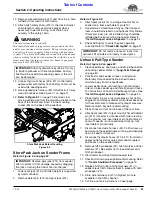
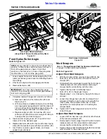
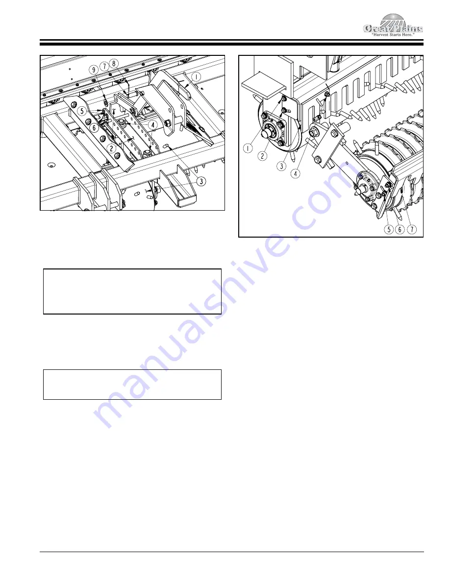
Front Spike Roller Adjustment
(Gang Slide #1 Shown Positioned Fully Back)
Figure 3-1
Front Spike Roller Angle
Refer to Figure 3-1:
1.
Lower seeder frame onto blocks keeping the front
rollers just above ground level and allowing them to
move freely.
2.
Shut tractor engine off and engage park brake.
3.
Remove bent pins (#6).
4.
If needed, readjust flange lock nuts (#4) as follows:
a. Remove cotter pin (#8), flat washer (#9) and
clevis pin (#7).
b. With an extension, tighten locknuts (#4) until they
are snug against gang slide (#2) and then back-off
1/3 turn (2 hex flats). Additional back-off may be
required if gang slide does not move easily.
c. Replace cotter pin (#8), flat washer (#9), and
cotter pin (#7). Bend one or more legs of cotter pin
to keep cotter pin from falling out.
5.
Operate roller angling lever (#1) to position front
rollers (#3) to the desired angle.
6.
Replace bent pins (#6) with one on each side of gang
slide (#2). Secure bent pins with hair pin cotters (#5).
7.
Start tractor, remove support blocks, and lower
seeder to ground level.
39016
NOTE:
Gang slide (#2) is shown in its furthest back
position. In this position, both bent pins (#6) are in
front of the gang slide as shown. In all other
positions, one bent pin is in back of the gang slide
and the other is in front of the gang slide.
IMPORTANT:
Lock nuts (#4) should allow gang
slide (#2) to move easily with minimum gap between
lock nuts and gang slide.
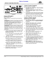
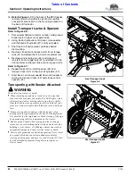
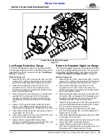
Mud Scraper Adjustments
Figure 3-2
Mud Scrapers
Refer to
“Torque Values Chart for Common Bolt Sizes”
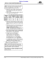
on page 70 when tightening hardware.
Refer to Figure 3-2:
Adjust Front Mud Scrapers
1.
With front rollers off the ground, loosen 3/8"-16 hex
bolts (#1 & #2) at both ends of the left front mud
scraper (#3).
2.
Rotate teeth of mud scraper towards the front roller to
increase removal of mud and debris and away if
scraper teeth are interfering with the roller.
3.
Tighten the four 3/8"-16 GR5 hex head
bolts (#1 & #2) to the proper torque.
4.
Repeat steps 1, 2 & 3 above for the right front mud
scraper.
5.
Loosen hex flange lock nuts (#4) and adjust front
scrapers (#3) left or right to align slots up with the
roller spikes. Rotate spike rollers one or more
revolutions to verify spikes are not touching the
scraper teeth.
6.
Tighten 3/8"-16 hex flange lock nuts (#4) to the
correct torque.
Adjust Rear Mud Scrapers
1.
Loosen 3/8"-16 hex lock nuts (#5 & #6) at both ends
of the rear mud scraper (#7).
2.
Rotate teeth of mud scraper toward the front roller to
increase removal of mud and debris and away if
scraper teeth are interfering with the roller.
3.
Tighten the four 3/8"-16 GR5 hex head bolts and lock
nuts (#5 & #6) to the proper torque.
39024
Section 3: Roller Adjustments

