2019-06-12
401-705M
YP3025A
173
Appendix C - Initial and Option Setup
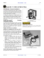
Seed Monitor Console Installation
The Planter’s standard seed monitor system includes a
virtual terminal and switch panel that must be mounted in
the tractor cab. As supplied by DICKEY-john®, the kit
includes a flat bracket for the modules, and a ball swivel
for mounting the bracket in the tractor.
The ball swivel includes four 10-32 base screws. You or
your dealer must provide the mounting holes for the
screws. Dealer may have alternate suction or clamping
brackets available if you prefer to avoid drilling holes.
Refer to the included DICKEY-john® manual for harness
connections.
Swath Command™ Console
Installation (Option)
The Auto Section Control terminal includes a second ball
swivel mount for cab installation. Pick a location that
does not obstruct view or interfere with tractor
operations. Use the included 10-32 screws to mount the
swivel. Use the included metric screws to attach the
console to the swivel.
Hopper Level Sensor Installation
Regardless of hopper/seed box used, the YP3025A
includes a factory-installed level sensor in the airbox.
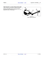
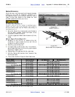
If a 403-143K 82 bu. or 403-174K 150 bu. hopper was
ordered with the Planter, it includes an 833-235C hopper
level sensor which is not factory-installed. This sensor
can provide a second, earlier, low seed level alarm.
Use of this sensor is optional, and level placement is at
your discretion. To install:
1. Perform the installation before first use of the
hopper. The sensor body is mounted inside the
hopper. It can be dangerous to enter a hopper if it
contains any seed, or has ever been used with
treated seed.
2. Refer to Figure 40 on page 38, or Figure 41 on
page 39 for placement elevations based on
remaining hopper capacity. Great Plains suggests
mounting on the lower front wall of the hopper.
3. Follow the steps in DICKEY-john® instruction sheet
11001-1126 to install the sensor.
4. Use silicone to seal the cable at the grommet, and
around the grommet, to prevent air leaks which can
interfere with consistent seed delivery.
After the hopper is mounted on the Planter, the leads
connect to the “HOPPER 2” harness lead located below
the hydraulic drive in the Planter center section.
Transport and Field Safety Risk:
Mount the modules so that they are easy to monitor during
planting, but do not interfere with safe operation of the tractor
in the field or on public roads.
Figure 150
Terminal and Switch Panel
26303
Figure 151
833-235C Hopper Level Sensor
29328

