11
❏
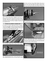
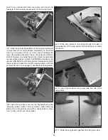
7. Use a felt-tip pen to mark the location where the pushrods
cross the outer holes of the fl ap servo arms.
❏
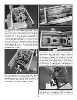
8. Just as you did with the aileron pushrods, bend each
pushrod at a 90 degree angle at the marks you made. Cut off
the excess pushrod 1/4" [6.4 mm] beyond the bends. Attach
the pushrods to the servo arms using nylon FasLinks.
❏
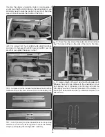
9. Wooden pins were installed at the factory that lock the
fl aps in place for those modelers who choose not to have
operational fl aps. Use a razor saw or similar tool to cut through
the pins (the pins can be seen by looking at the inboard ends
of the fl aps). Take care not to cut into the fl aps or wings.
❏
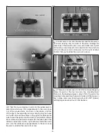
10. Test the operation of the fl aps with your radio system.
Unlike the ailerons, the fl aps will only move in the down
direction. If necessary, thread the clevises up or down on the
pushrods so that the fl aps are inline with the trailing edge of
the wings when the fl ap dial is rotated fully to its stop point.
When satisfi ed, slide the silicone clevis retainers to the end
of the clevises.
❏
11. You are now completed with the wing assembly. It can
be set aside as it will not be needed again until the fi nal setup
of the Avistar.
Glow Engine Installation
This section only contains information relevant to installing
a glow engine. Skip this section if you plan to install a
brushless motor.
❏
1. Cut 6-1/2" [165mm] from the included hook and loop
strap material. Join the two pieces together to make the fuel
tank strap by overlapping the mating ends 1" [25mm].
❏
2. Lift off the fuselage hatch by sliding it back and up. Route
the strap around the underside of the fuel tank tray. There are
notches on the sides of the tray for the strap.

