19
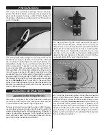
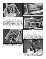
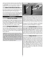
cap screw loosely threaded in it onto the top of the nose gear
wire up to the coil. Insert the nose gear wire into the steering
block and slide the steering arm onto the nose gear in the
orientation shown. Push the nose gear up as high as it will go
and tighten the screw in the collar that is resting against the
coil. Align the screw in the steering arm with the fl at spot on
the nose gear wire and tighten the screw in it. Ensure that the
nose gear wire turns freely inside the steering block.
❏
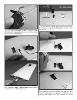
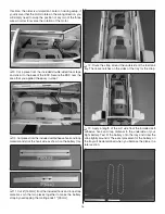
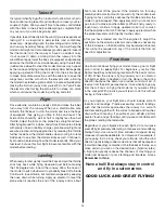
10. Slide the horizontal stabilizer into the stab slot in the aft
end of the fuselage. Push it as far forward as it will fi t. Center
the stab in the slot. Look down through the vertical fi n slot and
ensure that the cutout in the horizontal stabilizer is aligned
with the vertical fi n slot.
❏
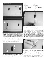
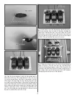
11. Fit the vertical fi n into the vertical fi n slot. The metal
posts in the fi n should pass through the holes in the bottom
of the fuselage.
❏
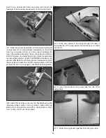
12. Locate the two EasyAlign tail bolts. Slide them into the
holes in the underside of the fuselage and onto the threaded
metal posts. The bolts should be tightened snugly so the tail
section is secure. Confi rm that the horizontal stabilizer and
vertical fi n cannot shift in their slots. Take care not to over-
tighten them as excessive force could damage the wood frame.
Install the Tail Surface Servos & Pushrods
This section shows the installation of the throttle servo and
pushrod for a glow engine. If you installed a brushless motor,
follow only the instructions written for the elevator and rudder
servos and ignore the throttle servo installation.
❏
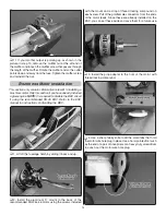
1. Locate the plywood tail servo tray. Use your radio
system to center your elevator, rudder, and throttle servo (if
you installed a glow engine). Move the throttle stick on your
transmitter to the middle position to center the throttle servo.
As you did with the aileron servos, use the hardware included
with the tail and throttle servos to mount them to the servo
tray. Use thin CA glue to harden the wood surrounding the
screw holes.


