11
Fixed Flaps
If you are not installing operational fl aps, follow these steps
to lock the fl aps into the neutral position. If in the future you
choose to add operational fl aps, simply cut the ABS strips
along the inside edge of each fl ap and install the fl ap servos
and linkage as described in previous steps.
❏
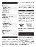
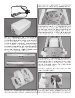
1. Locate the two 3/4" x 1-1/2" [19 x 38mm] ABS fl ap strips.
❏
2. Center the strips over the inside edge of each fl ap just
forward of the fl ap trailing edge. Use a felt-tip pen to trace
around the shape of the ABS fl ap strips onto the fl aps and
wing panels.
❏
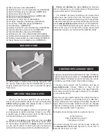
3. Carefully remove the covering approximately 1/16"
[1.6mm] inside the lines you drew using a sharp hobby knife.
Take care not to cut into the wood when cutting the covering.
❏
4. Wipe away the lines from the pen using a cloth
dampened with alcohol and glue the strips into position.
BUILD THE FUSELAGE
Install the Tail Surfaces
❏
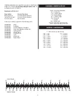
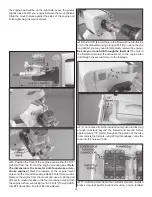
1. Place the horizontal stab onto the stab saddle in the
fuselage and align the three holes in the stab with the three
holes in the saddle. Align the holes in the vertical fi n base
with the holes in the stab. Press the forward end of the vertical
fi n into the slot in the fuselage. Use three 6-32 x 1" [25mm]
SHCS and threadlocking compound to bolt the vertical fi n
and horizontal stab to the fuselage. A strip of red covering is
provided to cover the screw holes if desired.
❏
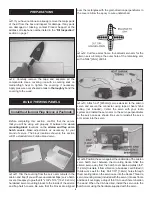
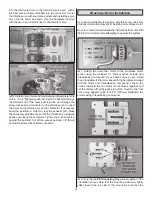
2. Temporarily insert a 36" [914mm] pushrod into the
elevator outer pushrod tube that exits the right side of
the fuselage. Use the position of the pushrod to mark the
location for the elevator control horn onto the underside of
the elevator.


