❏
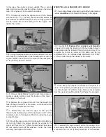
6. If using a glow engine, hook up the throttle using the
36" [910mm] wire pushrod. The threaded end of the pushrod
is connected to a 2-56 ball link on the carburetor arm with a
nylon ball link. The other end is cut to length, then connected
to the screw-lock connector on the throttle servo arm. If using
a gas engine, hook up the throttle using the 24" [610mm]
white plastic pushrod (as shown in the photos). The pushrod
is connected to a 2-56 ball link on the carburetor arm (or
bellcrank) with a 2-56 x 1" [25mm] threaded rod and a nylon
ball link. The other end is cut to length, then connected to the
screw-lock connector on the servo arm with a short piece of
wire cut from the threaded end of the 36" [910mm] wire
pushrod that is threaded into the plastic pushrod.
❏
7. Slide the plywood guide tube supports over the
throttle pushrod guide tube, then glue them inside the
fuselage where necessary to support the guide tube.
❏
8. Mount the muffler and cut a hole in the cowl for the
engine exhaust. If the exhaust outlet on the muffler does not
extend outside the cowl, use a suitable exhaust extension.
Note: If using the Fuji 50 engine, a portion of the right side
of the engine box will have to be trimmed to accommodate
the muffler. After trimming, lightly coat the exposed wood
with epoxy.
❏
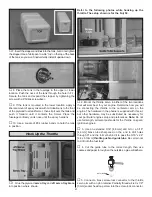
9. Connect the fuel lines. If using a glow engine, connect
the vent line coming from the fuel tank to the pressure tap
on the muffler. If using a gas engine, route the vent line out
the bottom of the cowl. For the Fuji gas engine setup shown
in the photo, a 1/4" [6.4mm] and a 1/8" [3.2mm] hole were
drilled through a basswood block (not included) to secure
the fueling line and the vent. A fuel line holder was made for
the fueling line by drilling a 1/4" [6.4mm] hole through a
basswood block (not included) and cutting a slot so the line
can be press-fit into the hole. If using a gas engine, be
certain the lines cannot contact the engine or muffler—most
fuel tubing used for gas engines will not stand up to heat. A
wire hook was made for the fuel line and screwed to F-1 so
the line would not contact the engine.
❏
10. If using an engine with a choke, make a pushrod so
the choke can be activated from outside the fuselage.
❏
11. Cut any other holes in the cowl where necessary for
the glow plug igniter, fueling system, muffler etc.
As stated in the IMAA Safety Code, all magneto spark
ignition engines must have a manually operated, coil-
grounding on/off switch to stop the engine and prevent
accidental starting. In addition to the required, manually
operated switch mounted outside the model, some pilots
may also elect to use a servo-operated on/off ignition switch.
This is not required, but could be installed for redundancy. A
servo-operated on/off ignition switch is also a good idea if
you have a spark-ignition engine that does not reliably shut
off by closing the carburetor.
For use with the Fuji engine shown, the manually operated
switch was made from a .3 Amp slide switch, 16 gauge wire
and a covered connector purchased at the local Radio
Shack.
®
Slightly different hardware may be required if using
a different spark-ignition engine. All of the components
required should be available at any hardware or home-
improvement store.
Mount the Kill Switch
(For Spark Ignition Engines Only)
32


