background image

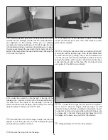
3. On the side of the engine mount are reference marks.

Align the marks that are in line with the engine mounting
rails with the lines on the firewall. Align the center of the
engine with the lines on the firewall. Tack glue the mount to
the firewall.

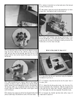
4. When positioning your engine, be sure the engine is

centered, but also be sure it is positioned so that the muffler
will be centered over the fiberglass cutout on the left side of
the fuselage. When you are satisfied with the position of the
engine, mark the location of the holes in the engine mount
onto the firewall.

5. Remove the engine mount from the firewall. Drill four 1/8"

[3mm] holes though the firewall on each of the four marks.

6. Install a 3mm blind nut on the back side of the firewall

in each of the four holes.

7. Mount the engine mount to the firewall with four 3 x 19mm

screws, 3mm lock washers and 3mm flat washers.

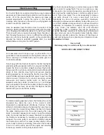
8. Drill a 3/32" [2.4mm] hole through the firewall, in line

with the throttle arm on the carburetor. Slide the white nylon
guide tube into the hole in the firewall, feeding it back to the
throttle servo. Cut the tube to length.

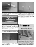
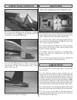
Refer to this photo for steps 9-12

9. Mount the throttle servo as shown using the hardware

included with your servo.

10. Install a screw-lock connector into the outer hole in

the servo arm.

11. Install the throttle pushrod wire into the tube. The 

Z-bend is installed in the throttle arm. Slide the opposite end
of the wire into the screw-lock connector. Adjust the servo
arm. Then tighten the set screw against the pushrod wire.

12. Support the throttle pushrod tube with a piece of

scrap balsa or plywood.

12

Summary of Contents for Combat Corsair

Page 1: ...this kit immediately in new and unused condition to the place of purchase To make a warranty claim send the defective part or item to Hobby Services at the address below Hobby Services 3002 N Apollo...

Page 2: ...at Corsair ARF If there is new technical information or changes to this model a tech notice box will appear in the upper left corner of the page We urge you to join the AMA Academy of Model Aeronautic...

Page 3: ...parts Vacuum the parts and the work area thoroughly after working with fiberglass parts Remember Take your time and follow the instructions to end up with a well built model that is straight and true...

Page 4: ...RING REPLACEMENT PARTS Replacement parts for the Great Planes 1 12 Combat Corsair ARF are available using the order numbers in the Replacement Parts List that follows The fastest most economical servi...

Page 5: ...398 8970 ext 5 Fax 217 398 7721 E mail airsupport greatplanes com KIT INSPECTION 1 Cowl 2 Fuselage 3 Cowl Ring 4 Wing Joiner 5 Engine Mount 6 Canopy 7 Belly Pan 8 Fuel Tank 9 Tail Cone 10 Fin with Ru...

Page 6: ...small just enough to see light through or to slip a piece of paper through Apply six drops of thin CA to the top and bottom of each hinge Do not use CA accelerator After the CA has fully hardened tes...

Page 7: ...wing Install and remove a servo mounting screw into each of the holes Insert a drop of thin CA into the holes to harden the wood After the glue has hardened mount the servo onto the blocks using the...

Page 8: ...ates over the wing bolt holes Use a fine point felt tip pen to trace the wing bolt plate location onto the wing Cut the covering away from the wing inside the lines you have drawn Use a sharp 11 hobby...

Page 9: ...lots for the stab and fin and the pushrod and antenna exits 2 If the wing is not mounted to the fuselage install the wing to the fuselage Insert the horizontal stab into the slot in the side of the fu...

Page 10: ...he fin to the fuselage using the same technique used for the stab 8 Remove the wing from the fuselage 9 Tape one of the elevators in place on the stab Center the elevator joiner wire then mark where t...

Page 11: ...stall the control horn the same way as was done with the ailerons 5 Center the servo Then tighten the set screw onto the pushrod wire 1 Assemble the fuel tank as shown in the sketch When tightening th...

Page 12: ...mm blind nut on the back side of the firewall in each of the four holes 7 Mount the engine mount to the firewall with four 3 x 19mm screws 3mm lock washers and 3mm flat washers 8 Drill a 3 32 2 4mm ho...

Page 13: ...Take into consideration the placement of the muffler when deciding exactly where the ring is to be placed 2 Drill a 1 16 1 6mm hole through each of the mounting tabs into the fuselage Mount the cowl...

Page 14: ...ing unplugged 4 Wrap the receiver and the battery in 1 4 6mm foam Secure them inside the fuselage with the balsa stick included in the kit 5 Turn on the radio system and make any adjustments required...

Page 15: ...wish to experiment by shifting the C G up to 1 8 3mm forward or 1 8 3mm back to change the flying characteristics Moving the C G forward may improve the smoothness and stability but the model may the...

Page 16: ...somewhere on your own you should always have your name address telephone number and AMA number on or inside your model It is required at all AMA R C club flying sites and AMA sanctioned flying events...

Page 17: ...d be connected to the engine coil Do not throw anything into the propeller of a running engine Read and abide by the following excerpts from the Academy of Model Aeronautics Safety Code For the comple...

Page 18: ...t however possess the self recovery characteristics of a primary R C trainer and should be flown only by experienced R C pilots A fully cowled engine may run at a higher temperature than an un cowled...

Page 19: ...come familiar with your model before landing To initiate a landing approach lower the throttle while on the downwind leg Allow the nose of the model to pitch downward to gradually bleed off altitude C...

Page 20: ...t settings creep Also includes glow plug and muffler OSMG0015 Displacement 0 152 cu in Bore 0 598 in Stroke 0 539 in Practical RPM 2 500 18 000 Output 0 41 bhp 17 000 rpm Weight 5 0 oz Displacement 0...

Reviews: