background image

1. If you have not done so already, remove the major parts

of the kit from the box and inspect for damage. If any parts
are damaged or missing, contact Product Support at the
address or telephone number listed in the “Kit Inspection”
section on page 5.

2. Remove the tape and separate the ailerons from the

wing and the elevators from the stab. Use a covering iron
with a covering sock on high heat to tighten the covering if
necessary. Apply pressure over sheeted areas to thoroughly
bond the covering to the wood.

Do the right top wing first, so your work matches the
photos the first time through. You can do one wing at a
time, or work on them together.

❏ ❏

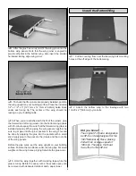
1. On the right top wing panel, drill a 3/32" [2.4mm]

hole, 1/2" [13mm] deep in the center of each hinge slot to
allow the CA to “wick” in. Follow-up with a #11 blade to clean
out the slots. Hint: If you have one, use a high-speed rotary
tool to drill the holes.

❏ ❏

2. Use a sharp #11 blade to cut a strip of covering

from the hinge slots in the wing and aileron.

❏ ❏

3. Cut four 3/4" x 1" [19 x 25mm] hinges from the CA

hinge strip. Snip off the corners so they go in easier.

❏ ❏

4. Test fit the ailerons to the wing with the hinges. If

the hinges don’t remain centered, stick a pin through the
middle of the hinge to hold it in position.

❏ ❏

5. Remove any pins you may have inserted into the

hinges. Adjust the aileron so there is a small gap between the
LE of the aileron and the wing. The gap should be small, just
enough to see light through or to slip a piece of paper through.

❏ ❏

6. Apply six drops of thin CA to the top and bottom of

each hinge. Do not use CA accelerator. After the CA has
fully cured, test the hinges by pulling on the aileron.

7. Repeat steps 1- 6 for the left top wing panel.

3/4"

[20mm]

1"

[25mm]

Installing the Ailerons

BUILD THE WINGS

PREPARATIONS

7

Summary of Contents for Curtiss P-6E Hawk

Page 1: ...to the place of purchase To make a warranty claim send the defective part or item to Hobby Services at the address below Hobby Services 3002 N Apollo Dr Suite 1 Champaign IL 61822 USA Include a letter...

Page 2: ...u will be pleased with its attention to detail and flight characteristics For the latest technical updates or manual corrections to the P 6E Hawk ARF visit the Great Planes web site at www greatplanes...

Page 3: ...lly training programs and instructors are available at AMA club sites to help you get started the right way Contact the AMA at the address or toll free phone number that follows Academy of Model Aeron...

Page 4: ...me hobby shops also sell it by the foot If only a small piece of MonoKote is needed for a minor patch perhaps a fellow modeler would give you some MonoKote is applied with a model airplane covering ir...

Page 5: ...4 40 x 1 2 SHC Screw 20 4 40 x 3 4 SHC Screw 4 4 Lock Washer 12 4 Nylon Lock Nut 8 4 Flat Washer 28 3 16 Axles 2 3 16 Wheel Collars 4 6 32 Set Screws 2 Nylon Axle Nut 2 2 x 3 8 Sheet Metal Screw 2 2...

Page 6: ...ces by calling 217 398 0007 or via facsimile at 217 398 7721 If ordering via fax include a Visa or MasterCard number and expiration date for payment Mail parts orders and payments by personal check to...

Page 7: ...up with a 11 blade to clean out the slots Hint If you have one use a high speed rotary tool to drill the holes 2 Use a sharp 11 blade to cut a strip of covering from the hinge slots in the wing and a...

Page 8: ...position the top wing upside down on your flat building surface The wing should lay flat If it does not remove the forward wing joiner flip it over and reinstall it in the wing panels 7 When you are s...

Page 9: ...to the joiner pockets in the wing This can be done by applying the glue into the pockets with a small stick Apply glue to the pockets the joiners and the root ribs of the wing panels Before the glue c...

Page 10: ...use 30 minute epoxy to glue the stabilizer to the fuselage Double check the stabilizer alignment while the epoxy is curing 1 Fit the fin in the cutout in the top of the stabilizer Make sure the bottom...

Page 11: ...he glue adhere to the stabilizer and fin 6 Glue the cover to the stabilizer fin and fuselage using CA epoxy or canopy glue We prefer to use epoxy or canopy glue to allow time to position the cover and...

Page 12: ...with a few dabs of silicone glue Using silicone will allow you to remove the belly pan easily should you ever have to get access to the landing gear bolts 3 Use a hacksaw or cutoff wheel on a rotary...

Page 13: ...the firewall 2 Press the four 8 32 blind nuts into the back of the firewall Use an 8 32 x 1 25 4mm socket head cap screw and 8 flat washer to fully seat the blind nuts in the firewall Apply a few dro...

Page 14: ...the engine hits the cowl Remove the cowl and cut a small hole in the cowl at the mark First cut the hole undersize checking the fit as you enlarge the hole 2 Use four pieces of thin cardboard or plas...

Page 15: ...side of the front plate to designate pressure 3 Install a piece of fuel tubing on each of the other two tubes Attach a clunk on the ends of the tubes Mark a C on the outside of the front plate by the...

Page 16: ...io tray in the former at the front of the wing saddle Carefully apply a drop of medium CA to the hardwood sticks at the aft edge of the radio tray Do not get CA on the radio tray Position the radio tr...

Page 17: ...ormers 9 Thread a nylon clevis 14 turns onto the 2 56 x 17 432mm metal pushrod Slide a silicone clevis retainer over the clevis Insert the pushrod in the outer pushrod tube and through the pushrod con...

Page 18: ...fuselage There are two located on the left side and one located on the right If you have trouble finding the openings slide a 096 x 36 914mm pushrod wire into the tubes from inside of the fuselage sli...

Page 19: ...t with the rudder control horn 5 Place your rudder servo into the servo tray as shown Drill a 1 16 1 6mm hole through each of the mounting holes Remove the servo then install and remove a servo mounti...

Page 20: ...to the same angle as the first elevator pushrod where the two meet 12 Cut the second elevator pushrod 1 4 6 4mm behind the solder clevis 13 Remove the first elevator pushrod and install two 3 16 whee...

Page 21: ...2 305mm pushrod Attach the clevis to a large control horn in the second hole from the bottom Position the control horn on the aileron so that the pushrod is inline with the outer hole in the aileron s...

Page 22: ...rough the threads to clear the glue 4 Mount the bottom wing cabane brackets in each of the holes in the right wing panel with a 4 40 x 1 2 13mm socket head cap screw and a 4 lock washer Do not fully t...

Page 23: ...of the top wing is much higher the N struts are possibly backwards 13 Drill a 5 64 2mm hole through each of the four mounting holes in the center cabanes When you drill these holes you must be drilli...

Page 24: ...and the remaining pieces fit properly glue the plywood parts to the handle 6 On the remaining handle part install a 4 40 blind nut into each of the corner holes 7 Place the two N struts into the handl...

Page 25: ...tions shown Install and then remove a 2 x 3 8 9 5mm sheet metal screw into each hole Remove the cover and then apply a couple of drops of thin CA into the holes in the box to harden the threads 1 Loca...

Page 26: ...ibed here will provide a reasonably scale appearance without the hassles typically associated with flying wires Because they are made from elastic there is no need to tension them each time you put th...

Page 27: ...he hole in the trailing edge of the fin 6 Continue threading the cord through the aft hole in the trailing edge of the stab on the opposite side of the fuselage and back down to the aft bottom of the...

Page 28: ...4mm above the wing Drill 5 64 2mm holes partially into the fuselage on each of the two marks 13 Put a small drop of CA on the cord then insert it into forward hole 14 Bring the elastic cord around the...

Page 29: ...the cord to the cabane with a small drop of CA 1 Use scissors or a sharp hobby knife to cut the decals from the sheet 2 Be certain the model is clean and free from oily fingerprints and dust Prepare a...

Page 30: ...prototypes had an O S 1 20 four stroke engine and required approximately 16 oz of lead This should be a good starting point for balancing your plane too After putting the lead in the box be sure to re...

Page 31: ...harge your transmitter and receiver batteries the night before you go flying and at other times as recommended by the radio manufacturer Note Checking the condition of your receiver battery pack is hi...

Page 32: ...y pack or a defective cell or a damaged receiver crystal from a previous crash Keep all engine fuel in a safe place away from high heat sparks or flames as fuel is very flammable Do not smoke near the...

Page 33: ...l refer to radio controlled model aircraft either scale or non scale which have a wingspan of 80 inches or more for monoplanes and 60 inches or more for multi winged model aircraft and have a ramp wei...

Page 34: ...un cowled engine For this reason the fuel mixture should be richened so the engine runs at about 200 RPM below peak speed By running the engine slightly rich you will help prevent dead stick landings...

Page 35: ...downward to gradually bleed off altitude Continue to lose altitude but maintain airspeed by keeping the nose down as you turn onto the crosswind leg Make your final turn toward the runway into the win...

Page 36: ...____________ Where Purchased _________________________ Date Construction Started __________________ Date Construction Finished _________________ Finished Weight __________________________ Date of Firs...

Reviews: