26
❏
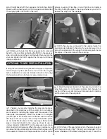
7. Choose a retract servo arm
that has a hole 1/2" [13mm] from
the servo arm center. Determine
the best orientation of the servo
arm onto the servo spline so that
it is parallel with the length of the
servo case as shown in the photo
of the next step. Install a screw
lock connector using a screw lock connector retainer into
the hole that is 1/2" [13mm] from the servo arm center of the
chosen arm. Loosely thread a 4-40 x 1/8" [3mm] SHCS into
the connector. The remaining servo arms can be cut off.
❏
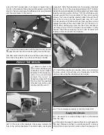
8. Install the servo arm onto the retract servo as shown.
❏
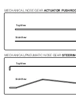
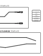
9. Make the mechanical
nose gear actuator pushrod
by threading a nylon clevis 20
turns onto a 17-1/2" [445mm]
pushrod, bending the pushrod
to clear the nose wheel. Use the
mechanical nose gear actuator
pushrod template in this manual
as a guide for the bend angles
and pushrod length.
Use the
template in
the center of
this manual as
a guide for the
bend angles
and pushrod
length.
Nylon
Clevis
17-1/2"
[445mm]
Pushrod
❏
10. Insert the pushrod through the hole you made in the
wheel well. Connect the clevis on the pushrod to the actuator
link on the nose gear retract and the other end to the screw
lock connector on the retract servo. Test the operation of the
retract servo using your radio system. Be sure that the retract
locks both in the up and down position. Make any adjustments
as necessary.
❏
11. Cut the included 5/32" x 1-1/4" [4mm x 32mm] bolt-on
axle to 1" [25mm] long as shown in the photo. Grind a fl at spot
at the end of the axle for the wheel collar set screw.


