background image

36

Balance the Model (C.G.)

More than any other factor, the

 C.G.

 (balance point) can 

have the 

greatest

 effect on how a model fl ies, and may 

determine whether or not your fi rst fl ight will be successful. 
If you value this model and wish to enjoy it for many fl ights, 

DO NOT OVERLOOK THIS IMPORTANT PROCEDURE.


A model that is not properly balanced will be unstable and 
possibly unfl yable.

At this stage the model should be in ready-to-fl y condition with 

all of the systems in place including the engine or brushless 
motor, landing gear, and the radio system (and battery pack 
if applicable).

❏ 

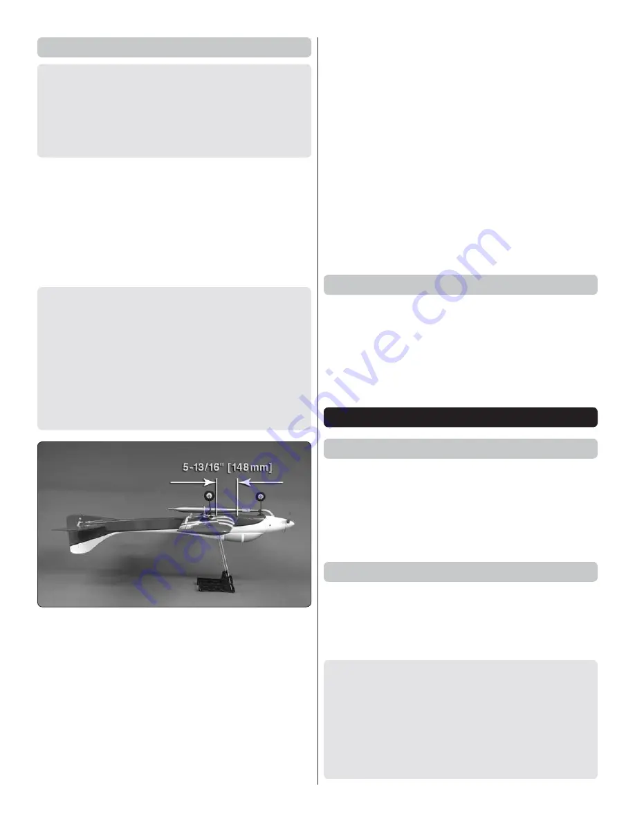
1. Use a felt-tip pen or 1/8" [3mm]-wide tape to accurately 

mark the C.G. on the top of the wing on both sides of the 
fuselage. The C.G. is located 5-13/16" [148mm] back from 
the leading edge of the wing.

This is where your model should balance for the fi rst fl ights. 
Later, you may wish to experiment by shifting the C.G. up 
to 11/16" [17.5mm] forward or 11/16" [17.5mm] back to 
change the fl ying characteristics. Moving the C.G. forward 
may improve the smoothness and stability, but the model 
may then require more speed for takeoff and make it more 
diffi cult to slow for landing. Moving the C.G. aft makes 
the model more maneuverable, but could also cause it to 
become too diffi cult to control. In any case, 

start at the 

recommended balance point 

and do not at any time 

balance the model outside the specifi ed range.

❏ 

2. With the wing attached to the fuselage, all parts of the 

model installed (ready to fl y) and an empty fuel tank, place 
the model on a Great Planes CG Machine upside down, or 
lift it at the balance point you marked.

❏ 

3. If the tail drops, the model is “tail heavy” and the battery 

pack and/or receiver must be shifted forward or weight must 
be added to the nose to balance. If the nose drops, the model 
is “nose heavy” and the battery pack and/or receiver must be 
shifted aft or weight must be added to the tail to balance. If 
possible, relocate the battery pack and receiver to minimize or 
eliminate any additional ballast required. If additional weight is 
required, nose weight may be easily added by using a “spinner 
weight” (GPMQ4645 for the 1 oz. [28g] weight, or GPMQ4646 

for the 2 oz. [57g] weight). If spinner weight is not practical or 
is not enough, use Great Planes (GPMQ4485) “stick-on” lead. 

A good place to add stick-on nose weight is to the fi rewall 
(don’t attach weight to the cowl—it is not intended to support 

weight). Begin by placing incrementally increasing amounts 
of weight on the bottom of the fuse over the fi rewall until the 
model balances. Once you have determined the amount of 
weight required, it can be permanently attached. If required, 
tail weight may be added by cutting open the bottom of the 
fuselage and gluing it permanently inside.

Note:

 Do not rely upon the adhesive on the back of the lead 

weight to permanently hold it in place. Over time, fuel and 
exhaust residue may soften the adhesive and cause the weight 
to fall off. Use #2 sheet metal screws, RTV silicone or epoxy 
to permanently hold the weight in place.

❏ 

4. 

IMPORTANT:

 If you found it necessary to add any weight, 

recheck the C.G. after the weight has been installed.

Balance the Model Laterally

❏ 

1. With the wing level, have an assistant help you lift the 

model by the engine propeller shaft and the bottom of the 
fuse under the TE of the fi n. Do this several times.

❏ 

2. If one wing always drops when you lift the model, it means 

that side is heavy. Balance the airplane by adding weight to the 
other wing tip.

 An airplane that has been laterally balanced 

will track better in loops and other maneuvers.

PREFLIGHT

Identify Your Model

No matter if you fl y at an AMA sanctioned R/C club site or 
if you fl y somewhere on your own, you should always have 
your name, address, telephone number and AMA number 
on or inside your model. It is 

required

 at all AMA R/C club 

fl ying sites and AMA sanctioned fl ying events. Fill out the 
identifi cation tag on the center template page and place it on 
or inside your model.

Charge the Batteries

Follow the battery charging instructions that came with your 
radio control system to charge the batteries. You should always 
charge your transmitter and receiver batteries the night before 
you go fl ying, and at other times as recommended by the 
radio manufacturer.

CAUTION:

 Unless the instructions that came with your 

radio system state differently, the 

initial 

charge on 

new 

transmitter and receiver batteries should be done for 15 
hours 

using the slow-charger that came with the radio 

system

. This will “condition” the batteries so that the next 

charge may be done using the fast-charger of your choice. 
If the initial charge is done with a fast-charger the batteries 
may not reach their full capacity and you may be fl ying with 
batteries that are only partially charged.

Summary of Contents for DIRTY BIRDY .60 ARF

Page 1: ...user assembled product By the act of using the user assembled product the user accepts all resulting liability If the buyer is not prepared to accept the liability associated with the use of this prod...

Page 2: ...ndanger insurance coverage Additionally training programs and instructors are available at AMA club sites to help you get started the right way There are over 2 500 AMA chartered clubs across the coun...

Page 3: ...r working with fiberglass parts We as the kit manufacturer provide you with a top quality thoroughly tested kit and instructions but ultimately the quality and flyability of your finished model depend...

Page 4: ...utting bit Revell Premium Soft Handle Knife w Blades 5 RMXR6900 Top Flite MonoKote sealing iron TOPR2100 Top Flite Hot Sock iron cover TOPR2175 Panel Line Pen TOPQ2510 Hobbico Steel T Pins 1 100 HCAR5...

Page 5: ...parts to make sure they are of acceptable quality If any parts are missing or are not of acceptable quality or if you need assistance with assembly contact Product Support When reporting defective or...

Page 6: ...o thoroughly bond the covering to the wood ASSEMBLE THE WINGS Cut Off Unused Arms 5 64 2mm 1 Center your aileron servos and trims with your radio system Test fit four armed servo arms onto the servos...

Page 7: ...through the mounting tabs on the servo cases into the rails Thread a servo mounting screw included with the servo into each hole and back it out Apply a drop of thin CA to each hole to harden the wood...

Page 8: ...rs to the ends of the clevises to secure them 9 Prepare the aluminum wing joiner piece by roughening both sides of it with 180 220 grit sandpaper Clean the piece with denatured alcohol Use epoxy to la...

Page 9: ...the other photos in this section to determine the correct orientation of the blocks Drill through the four mounting holes on each block and into the wood rails in the wing using a 5 64 2mm bit 2 Remov...

Page 10: ...the instructions that came with the retract set with tool in hand adjust the nose retract as well Removing the free play ensures that the plane will taxi straight and smoothly down the runway Do not s...

Page 11: ...a later section Grind a flat spot at the end of each axle using a flat spot or rotary tool 8 Slide a wheel onto each axle and secure them with a 5 32 4mm wheel collar 6 32 x 1 4 6mm SHCS and thread l...

Page 12: ...deep as the knife blade will allow Use a small flat blade screw driver to work out the portion that you have so far cut away Use a rotary tool with a sanding drum bit to remove most of the remaining m...

Page 13: ...e turns onto a 12 305mm pushrod Insert the pushrod through the hole at the inboard side of a wheel well Align the pin in the clevis over the actuator link on the retract when the retract is in the dow...

Page 14: ...wells on the underside of the wing There are small pieces of wood supporting the covering that must also be removed 2 Open the pneumatic retract cases and flip the positions of the valves to the oppo...

Page 15: ...glue to harden 7 Turn the wing over and measure back 5 127mm from the center leading edge of the wing and make a mark approximately 1 2 13mm on each side of the seam of the wing panels Cut a 5 16 to...

Page 16: ...he wheel collars using 6 32 set screws and thread locking compound 13 Loosely install a 6 32 x 1 4 6 4mm SHCS into each axle Slide the axles onto the retract struts and raise the wheels into the wheel...

Page 17: ...from Balsa Use a soldering iron to cut the covering from the area beneath the belly pan The tip of the soldering iron doesn t have to be sharp but a fine tip does work best Allow the iron to heat ful...

Page 18: ...age taking care to wipe away any excess epoxy that squeezes out as you slide the halves together Clean around the roots of the stab halves and then use masking tape to hold the stab halves tightly aga...

Page 19: ...ts with the clevises to bring the elevator halves perfectly parallel with each other 9 Install the rudder control horn using the remaining 2 56 x 36 914mm pushrod The clevis should be connected to the...

Page 20: ...e sealed off fuel tube hole The fill and carb lines should extend out 1 2 13mm beyond the stopper and the vent line should be bent upwards and left uncut With the tubes installed in the stopper fit th...

Page 21: ...Carefully remove this insert in order to use your full size templates on the reverse side...

Page 22: ...MECHANICAL NOSE GEAR ACTUATOR PUSHROD MECHANICAL PNEUMATIC NOSE GEAR STEERING Top View Side View Top View Side View...

Page 23: ...D TEMPLATE G PUSHROD TEMPLATE This model belongs to Name Address City State Zip Phone Number AMA Number...

Page 24: ...Carefully remove this insert in order to use your full size templates on the reverse side...

Page 25: ...it in place behind the fuel tank to secure it 6 Connect a 6 7 152 178mm piece of standard fuel tubing to each tube protruding from the fuel tank 7 Position the front of the engine drive washer 4 5 8 1...

Page 26: ...e hole you drill does not pass into the wheel well on the underside of the fuselage for a retractable nose gear Align the drill bit so the throttle pushrod will be positioned in the space between this...

Page 27: ...the collar onto the end of the nose gear wire as shown Tighten the set screw against the flat spot on the wire Tighten the SHCS in the steering arm against the other flat spot Ensure that the nose gea...

Page 28: ...nel on your receiver Otherwise connect servo extensions to the channels you will mix together for the ailerons Wrap your receiver in 1 4 6 4mm foam rubber not included Fit the receiver into the cavity...

Page 29: ...shown in step 11 onto the end of the gear strut to ensure the nose wheel will be centered in the wheel well Center the retract between the rails and use a felt tip pen to mark the mounting hole locati...

Page 30: ...5mm pushrod bending the pushrod to clear the nose wheel Use the mechanical nose gear actuator pushrod template in this manual as a guide for the bend angles and pushrod length Use the template in the...

Page 31: ...ight enough to hold the axle in place on the strut Move the retract to the down position Rotate the axle on the wire so the nose wheel will point straight ahead with the nose gear strut pointing strai...

Page 32: ...ocate the two small nylon disks and two nylon torque rod horns as shown These parts will be used as steering pushrod guides 17 Remove the steering pushrod from the fuselage Slide the torque rod horns...

Page 33: ...e dimensions shown A rotary tool with a cut off wheel is recommended for shortening the strut 3 Position the retract onto the rails in the retract well as far forward as it will go Use a felt tip pen...

Page 34: ...s will prevent them from interfering with the wing Use a pair of pliers to snug down the knurled nut Use thick CA or epoxy to glue the valve mount to the servo tray in the location shown 10 Make an ac...

Page 35: ...g pushrod from the fuselage Slide the torque rod horns onto the pushrod and reinstall the pushrod in the fuselage Space them evenly apart as shown and mark the positions of the mounting holes onto the...

Page 36: ...at will connect to the main gear 20 Cut the included 5 32 x 1 1 4 4mm x 32mm bolt on axle to 1 25mm long as shown in the photo Grind a flat spot at the end of the axle for the wheel collar set screw 2...

Page 37: ...use tie straps to secure it if you have not yet tuned the system do not install the tie straps on the coupler yet Because the pipe is mounted directly to the wing we chose to use an in line connector...

Page 38: ...approximately 3 32 2 4mm behind the spinner backplate also while centering it Temporarily tape the cowl into position Drill four 1 16 1 6mm holes evenly spaced around the cowl perimeter for the cowl...

Page 39: ...UP STANDARD MODE 2 3 Make certain that the control surfaces and the carburetor respond in the correct direction as shown in the diagram If any of the controls respond in the wrong direction use the se...

Page 40: ...ace to add stick on nose weight is to the firewall don t attach weight to the cowl it is not intended to support weight Begin by placing incrementally increasing amounts of weight on the bottom of the...

Page 41: ...that engine exhaust gives off a great deal of deadly carbon monoxide Therefore do not run the engine in a closed room or garage Get help from an experienced pilot when learning to operate engines Use...

Page 42: ...G according to the measurements provided in the manual 2 Be certain the battery and receiver are securely mounted in the fuse Simply stuffing them into place with foam rubber is not sufficient 3 Exten...

Page 43: ...e with plenty of fuel practice slow flight and execute practice landing approaches by reducing the throttle to see how the model handles at slower speeds Add power to see how the model climbs as well...

Page 44: ...GPMA1975 Mnl Entire Contents 2011 Hobbico Inc All rights reserved...

Reviews: