7
to being perpendicular with the servo case with the transmitter
trims centered. Cut three arms from each servo arm leaving
one arm on each servo that matches the photo. Enlarge the
outer hole of each remaining arm with a 5/64" [2mm] drill bit.
Install the rubber grommets and eyelets.
❏
2. Attach a 12" [305mm] servo extension to each servo.
Secure the connection using tape, heat shrink tubing (not
included) or special clips designed for that purpose.
❏
3. Use the strings taped inside the aileron servo openings
to pull the servo leads through the wing panels.
❏
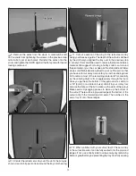
4. Fit the servos into the servo openings and drill 1/16"
[1.6mm] holes through the mounting tabs on the servo cases
into the rails. Thread a servo mounting screw (included with
the servo) into each hole and back it out. Apply a drop of thin
CA to each hole to harden the wood surrounding the wood.
When the CA has dried, install the servos into the openings
as shown using the screws supplied with the servos.
❏
5. Thread a nylon clevis onto each of the two 6" [152mm]
pushrods 20 complete turns. Slide a silicone clevis retainer
onto the base of each clevis. Attach each clevis to the outer
hole of a large control horn.
Hinge Line
Hinge Line
CORRECT
INCORRECT
❏
6. Position a control horn onto the aileron aligning the
pushrod with the outer hole of the aileron servo arm. Position
the control horns over the plywood plates in the ailerons (if
you cannot see them, hold the aileron at a shallow angle in


