❏ ❏
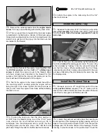
4. Center the elevator, then mark the pushrod where
it crosses the servo horn hole. Enlarge the servo horn hole
with a 5/64" drill bit. Make a 90 degree bend in the pushrod
on the mark. Cut off the excess wire 3/8" above the bend.
Insert the bent wire through the enlarged hole in the servo
horn. Secure it in place with a Nylon FasLink. (Doesn’t this
sound similar to the same procedure used for the aileron
pushrods?) Note the position of the FasLink in step 7.
❏
5. Repeat steps 3 and 4 for the rudder pushrod.
❏
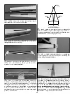
6. Assemble the 17-1/2" throttle pushrod by installing a
nylon clevis and silicone retainer onto the threaded end.
Cut four 1/4" bushings and install them 2-1/2" apart. Slide
the throttle pushrod into its outer tube (from the firewall in),
then through the pushrod connector. Attach the clevis to
the control arm of the carburetor.
❏
7. With the radio on, move the throttle trim lever and
control stick to the fully closed position, by pulling them
back (or downward) all the way. Manually close the throttle
on the carburetor completely. Tighten the set screw on the
pushrod connector. Check throttle operation with the radio
and make adjustments to the linkage as necessary for
smooth operation from fully closed to fully open.
Use the
appropriate holes in the servo horn and throttle arm to
provide the correct amount of throttle movement and to
prevent the servo from binding at its end points.
❏
8. Cut four 1/4" bushings and slide them onto the
remaining 17-1/2" pushrod 3" apart, starting 2-1/2" from
the non-threaded end. Bend the rod 90 degrees 1/2" from
the non-threaded end.
❏
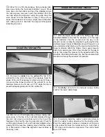
9. Drill a 5/64" hole through the
center
hole in the nose
gear steering arm. Insert the straight end of the steering
pushrod (from the firewall in) into the pushrod tube, into the
pushrod connector on the rudder servo. (Don’t cut the wire
or tighten the connector yet.) Work the wire into the
steering arm as shown in the photo.
❏
10. Turn the radio on. Check that the rudder trim is
centered. Align the nose wheel axle with the firewall by
moving the pushrod. When the axle is parallel with the
firewall, tighten the set screw on the pushrod connector.
❏
11. Using the leftovers that were saved from the servo
tray, make small stand-offs to secure the ends of the
throttle and nose wheel pushrods. Avoid getting any glue
inside of the pushrod tubes.
❏
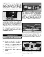
12. Drill a 1/16" hole through the bottom center of the
fuselage in front of the main landing gear block. Route the
receiver antenna through this hole. Put a small pin in the rear
of the fuselage. Use a rubber band tied around the antenna
wire and loop it around the pin to secure the antenna.
Note
: Do not cut or shorten the antenna wire. Leave any
excess to hang free.
❏
13. Once the model has been properly balanced, use
“popsicle sticks” or leftover wood glued between the fuse
sides to hold the receiver and battery securely in place.
18


