❏
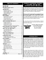
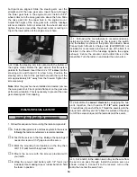
1. Remove the center spreader from the
engine mount
halves
. Trim any excess flashing with a hobby knife or file.
❏
2. This is a good time to fuelproof the tank and engine
compartments. Lightly brush a mixture of 30-minute epoxy
thinned with isopropyl alcohol into both compartments. Be
careful not to get any of the epoxy into the blind nuts that
are located in the firewall.
❏
3. Fit the two halves of the engine mount together. Use
four
#6 flat washers
and four
6-32 x 1" phillips head
screws
to attach the engine mount to the firewall. Blind
nuts have already been installed in the firewall for this
purpose. Don’t tighten the screws completely yet, as the
mount will need to be adjusted to fit the engine.
❏
4. Test fit the engine to the mount. Adjust the width of
the mounting rails to accommodate the engine without
being too tight or too loose. Tighten the mount screws so
that you can mark the engine screw holes without allowing
the rails to move.
❏
5. Position the engine so that the drive washer is
4-15/16" from the firewall. Using one of the 17-1/2" push
rods, sharpen the non-threaded end using a file or
sandpaper. Use this sharpened wire to scribe the four
mounting holes onto the rails. Use a 7/64" drill bit to drill
pilot holes through the rails for the #6 sheet metal screws.
❏
6. Attach the engine to the rails using four #6 x 3/4"
sheet metal screws.
❏
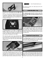
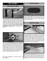
1. Separate the two die-cut 1/8" (3.2mm) ply parts of the
servo tray assembly,
then lightly sand off any rough spots
from the edges.
Save the excess plywood for use in
later steps.
❏
2. Test fit the servo tray assembly by first placing the
front brace
behind
the landing gear mounts. The servo tray
is then installed by “locking” it into the cut-out of former #4
and the front brace. When satisfied with the fit of these
components, glue them in place using medium CA. Be sure
to make a fillet along the joint between the servo tray and
the fuselage side.
❏
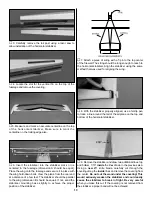
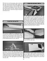
1. Measure and cut a 21" length from each of the two
outer pushrod tubes
supplied. The 21" pieces will be
used for the rudder and elevator. Save the pieces that were
cut off for the nose gear and throttle pushrods.
❏
2. Locate the pushrod exit slot under the covering on
the tail section of the fuselage by lightly pressing with your
fingers. The slot should be located 3-3/4" from the rear the
fuselage and 7/8" from the bottom of the fuselage. Trim the
covering to provide access to the pushrod exit. Check the
Install the Pushrod Tubes
Install the Servo Tray
#6 x 5/8" Sheet Metal Screw (4)
8


