2. Using any lightweight, good quality covering film
and following the manufacturer's instructions, cover your
model in the following sequence:
D 1. Rudder left side
D 2. Rudder right side
D 3. Elevator bottom
D 4. Elevator top
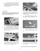
D 5. Cut 1/2" strips of covering, and apply to the joints
between the stab and fuse, the stab and fin, and the
dorsal fin and fuse.
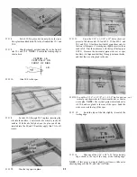
D 6. Stab bottom
D 7. Stab top
D 8. Fin left side
D 9. Fin right side
D 10. Fuse bottom
D 11. Fuse sides
D 12. Fuse top
D 13. Wing tips (overlap slightly onto wing surface)
D 14. Bottom o f w i n g ( m a y b e d o n e i n o n e o r t w o p i e c e s )
D 15. Wing fairing
D 16. Top of wing (may be done in one or two pieces)
D 17. Bottom of ailerons
D 18. Top of ailerons
D 19. Now cut out the openings in the covering for the
rudder cable exits, radio switch, landing gear,
aileron servo and wing bolt.
NOTE: If you are not using a landing gear, you may install a strip
of protective plastic or a small nylon skid on the fuse bottom.
Although this is not usually necessary for belly landing on smooth
grass, it may help to avoid scuffing or tearing the covering material.
ADD TRIM
Add trim using covering film or self-adhesive trim
material or decals. NOTE: We recommend that you keep
your trim scheme as simple as possible for ease of applica-
tion and to avoid weight build-up. We also recommend that
you trim with a contrasting color (light over dark, or dark
over light) for maximum visibility.
FINAL ASSEMBLY
hinge, making sure it flows into the hinge slots. Be prepared
to wipe off any excess glue with a tissue. IMPORTANT:
When installing the hinges, make sure there is little or no
hinge gap. A large (1/32" or more) hinge gap will reduce
control surface effectiveness, and may promote flutter!
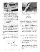
D 3. Re-install the nylon control horns. Cut off any
excess 2-56 screws that protrude through the nutplates.
IMPORTANT: Make sure the nutplate and screws of the elevator
horn do not touch the rudder when the elevator is deflected fully up!
Note: Photo shows uncovered structure.
D 4. Re-install the motor, wiring and all radio equip-
ment, including the radio on-off switch. NOTE: Depend-
ing on the radio you are using, it may be necessary to use
extra "aileron extension cords" from the receiver to the
speed control and from the switch to the receiver, due to the
aft location of the receiver.
INSTALL ALL COMPONENTS
D 1. Lay the rudder, elevators and ailerons on the plans
and mark on the leading edge of each part the locations of the
hinges. Now use a sharp Xacto knife to cut slits in the
covering at the hinge locations. Trial fit the hinges to make
sure you have "found" the slots which you previously cut. In
the same manner, slit the covering at the hinge locations in
the wing, stab and fin TE.
D 2. Glue the hinges in place. NOTE; We recommend
gluing the hinges with 30-minute epoxy (force glue into the
hinge slots with a plastic soda straw); however, we have also
had good success using thin CA glue. If you use thin CA,
assemble the parts first, then carefully apply the glue to the
Note: Photo shows uncovered structure.
D 5. Re-install the elevator and aileron pushrods.
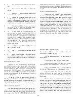
D 6. Install the EZ Connector onto the elevator servo
arm as shown on the plan, and pass the elevator pushrod wire
through the EZ Connector. Install the slotted screw to
secure the elevator pushrod.
E-Z CONNECTOR
30


