background image

5

ASSEMBLE THE FUSELAGE

Install the Horizontal and

Vertical Stabilizer


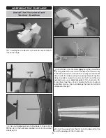
 1. Carefully fl ex the elevator up and down several times to 

loosen the hinge.


 2. Use a straightedge and a hobby blade to fi nish cuttting 

out the slot in the horizontal stabilizer (stab) for the vertical 
stabilizer (fi n).


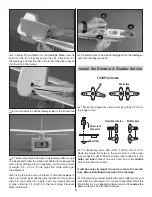
 3. Test fi t the fi n into the stab. 

Lightly

 spray the parts where 

they fi t together with a mist of CA accelerator and allow to dry 
for about 30 seconds to a minute. This “priming” procedure will 
allow the CA to harden quickly when gluing the parts together. 
Using a builder’s square to make sure the fi n and stab are 
perpendicular, use a 

small amount

 of thin, foam-safe CA 

to glue them together—do not saturate the foam or build up 
large fi llets of glue—this could damage the foam and will add 
unnecessary weight!

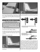
 4. Cut the 

spacers

 from the slot on both sides and on the 

top of the fuselage for the fi n and stab.

Summary of Contents for EP FALCON ARF

Page 1: ...the final user assembled product By the act of using the user assembled product the user accepts all resulting liability If the buyer is not prepared to accept the liability associated with the use o...

Page 2: ...ACADEMY OF MODEL AERONAUTICS 5151 East Memorial Drive Muncie IN 47302 9252 Tele 800 435 9262 Fax 765 741 0057 Or via the Internet at http www modelaircraft org http www modelaircraft org park yer asp...

Page 3: ...ElectriFly Triton EQ AC DC Charger GPMM3155 And in addition to its LiPo capability the Triton EQ also features one more critical component which is a built in LiPo cell balancer For the best LiPo perf...

Page 4: ...rizontal Stabilizer 4 Wing 5 Aileron Pushrods 6 Rudder Elevator Pushrods 7 Wing Center Doubler 8 Canopy 9 Main Wheels 10 Main Landing Gear 11 Nose Wheel 12 Rubber Bands 13 Fiber Reinforcement Tape KIT...

Page 5: ...ere they fit together with a mist of CA accelerator and allow to dry for about 30 seconds to a minute This priming procedure will allow the CA to harden quickly when gluing the parts together Using a...

Page 6: ...ing it to wick into the foam along the seam Remove the pins 9 Carefully insert the main landing gear into the fuselage note that the legs sweep aft Install the Elevator Rudder Servos ES40 Pico Servos...

Page 7: ...come through the bottom of the servo tray 6 Fit then glue the servo tray into position although the parts you are gluing here are balsa and regular CA could be used foam safe CA is still recommended...

Page 8: ...ening hole in the bottom of the fuselage just ahead of the landing gear Then connect the wires to the receiver Also connect a 6 150mm servo extension wire to the aileron channel in the receiver 8 Moun...

Page 9: ...ector to lock the pushrods down don t forget to add a small drop of threadlocker on the threads of the screws Finish the Wing The wing may be finished in either of two configurations one for indoor fl...

Page 10: ...Use a fine point felt tip pen to mark the ends of the C G lines on the template onto the wing 6 Use a straightedge to draw lines connecting the dots depicting the recommended balance range 7 Finally a...

Page 11: ...e the elevator throw first 3 Hold a ruler to the trailing edge of the elevator Note the measurement 4 Use the transmitter to move the elevator to full up and note how far the elevator moved This is th...

Page 12: ...motor complete radio system ESC propeller and battery 1 With the wings held to the fuselage with a couple of rubber bands lift the model by your fingers placed on the middle lines on the bottom of the...

Page 13: ...our face or eyes Keep your face and body as well as all spectators away from the plane of rotation of the propeller as you start and run the motor Keep loose clothing shirt sleeves ties scarfs long ha...

Page 14: ...o prepare for this with plenty of altitude until you get a feel for how it responds The rudder and elevator are more responsive One final note about flying your model have a goal or flight plan in min...

Page 15: ...G 3 0 76mm 2 5 8 67mm 2 1 4 57mm Forward C G Recommended C G Aft C G 3 0 76mm 2 5 8 67mm 2 1 4 57mm Forward C G Recommended C G Align with leading edge of wing Spare C G Marking Template This model b...

Page 16: ......

Reviews: