background image

25

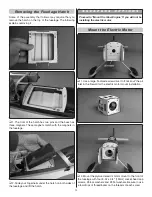
Balance the Model Laterally

 1. With the wing level, have an assistant help you lift the 

model by the engine propeller shaft and the bottom of the 
fuse under the TE of the fi n. Do this several times.

 2. If one wing always drops when you lift the model, it means 

that side is heavy. Balance the airplane by adding weight to the 
other wing tip.

 An airplane that has been laterally balanced 

will track better in loops and other maneuvers.

PREFLIGHT

Identify Your Model

No matter if you fl y at an AMA sanctioned R/C club site or if 
you fl y somewhere on your own, you should always have your 
name, address, telephone number and AMA number on or 
inside your model. It is 

required

 at all AMA R/C club fl ying sites 

and AMA sanctioned fl ying events. Fill out the identifi cation 
tag on page 28 and place it on or inside your model.

Charge the Batteries

Follow the battery charging instructions that came with your 
radio control system to charge the batteries. You should always 
charge your transmitter and receiver batteries the night before 
you go fl ying, and at other times as recommended by the 
radio manufacturer.

CAUTION:

 Unless the instructions that came with your 

radio system state differently, the 

initial 

charge on 

new 

transmitter and receiver batteries should be done for 15 
hours 

using the slow-charger that came with the radio 

system

. This will “condition” the batteries so that the next 

charge may be done using the fast-charger of your choice. 
If the initial charge is done with a fast-charger, the batteries 
may not reach their full capacity and you may be fl ying with 
batteries that are only partially charged.

Balance the Propellers

Carefully balance your propeller and spare propellers before 
you fl y. An unbalanced prop can be the single most signifi cant 
cause of vibration that can damage your model. Not only 
will engine mounting screws and bolts loosen, possibly with 

disastrous effect, but vibration may also damage your radio 
receiver and battery. Vibration can also cause your fuel to 
foam, which will, in turn, cause your engine to run hot or quit. 

We use a Top Flite Precision Magnetic Prop Balancer 
(TOPQ5700) in the workshop and keep a Great Planes 
Fingertip Prop Balancer (GPMQ5000) in our fl ight box.

Ground Check and Range Check

Run the engine for a few minutes, making sure it idles reliably, 
transitions smoothly and maintains full power indefi nitely. 

Afterward, shut the engine off and inspect the model closely, 

making sure all fasteners, pushrods and connections have 
remained tight and the hinges are secure. Always ground check 
the operational range of your radio before the fi rst fl ight of the 
day following the manufacturer’s instructions that came with 

your radio. This should be done once with the engine off and 
once with the engine running at various speeds. If the control 

surfaces do not respond correctly, 

do not fl y!

 Find and correct 

the problem fi rst. Look for loose servo connections or broken 
wires, corroded wires on old servo connectors, poor solder 
joints in your battery pack or a defective cell, or a damaged 
receiver crystal from a previous crash.

ENGINE SAFETY PRECAUTIONS

Failure to follow these safety precautions may result 
in severe injury to yourself and others.

Keep all engine fuel in a safe place, away from high heat, 
sparks or fl ames, as fuel is very fl ammable. Do not smoke 
near the engine or fuel; and remember that engine exhaust 
gives off a great deal of deadly carbon monoxide. Therefore


do not run the engine in a closed room or garage

.

Get help from an experienced pilot when learning to operate 
engines. 

Use safety glasses when starting or running engines.

Do not run the engine in an area of loose gravel or sand; the 
propeller may throw such material in your face or eyes.

Keep your face and body as well as all spectators away from 
the plane of rotation of the propeller as you start and run the 
engine.

Keep these items away from the prop: loose clothing, shirt 
sleeves, ties, scarfs, long hair or loose objects such as pencils 
or screwdrivers that may fall out of shirt or jacket pockets into 
the prop.

Use a “chicken stick” or electric starter to start the engine. 
Do not use your fi ngers to fl ip the propeller. Make certain the 

glow plug clip or connector is secure so that it will not pop off 
or otherwise get into the running propeller. 

Make all engine adjustments from behind the rotating propeller.

The engine gets hot! Do not touch it during or right after 

operation. Make sure fuel lines are in good condition so fuel 
will not leak onto a hot engine, causing a fi re.

Summary of Contents for ESCAPADE .61

Page 1: ...user of the final user assembled product By the act of using the user assembled product the user accepts all resulting liability If the buyer is not prepared to accept the liability associated with th...

Page 2: ...ood condition a correctly sized engine and other components as specified in this instruction manual All components must be correctly installed so that the model operates correctly on the ground and in...

Page 3: ...LiPo batteries FlightPower EONX 30 5000 mAh 3s 11 1V 30C LiPo FPWP6698 ElectriFly Series 2 Deans Male Ultra Plug 1 Deans Female Ultra Plug Adapter If experimenting with different batteries make certa...

Page 4: ...is specified it is highly recommended that you use only 30 minute or 45 minute epoxy because you will need the working time and or the additional strength Photos and sketches are placed before the ste...

Page 5: ...elephone at 217 398 8970 Order No Description REPLACEMENT PARTS LIST GPMA4135 GPMA4136 GPMA4137 GPMA4138 GPMA4139 GPMA4140 GPMA4141 GPMA4142 GPMA4143 GPMA4144 GPMA4145 Fuselage Escapade 61 ARF Wing Es...

Page 6: ...e string in the wing to pull the servo extension out the end and place the aileron servo in the wing 3 Temporarily mount the servo with the screws that came with it Drill 1 16 1 6mm holes for the serv...

Page 7: ...over the clevis 7 Making sure the servo and the aileron are centered use a fine point felt tip pen to mark the pushrod wire where it crosses the outer hole in the servo arm 8 Make a 90 bend in the wi...

Page 8: ...gs together and installing the screws Later during final radio and control throws set up the pushrods will be adjusted so the ailerons are centered when the radio is on or you could reconnect your ail...

Page 9: ...commended Add a drop of threadlocker to the threads of the wires Then tighten the assembly to the fuselage with a 4 flat washer a 4 lock washer and a 4 40 lock nut on each rod The included socket tool...

Page 10: ...same way you mounted the aileron servo s mount the rudder servo with the servo screws that came with them Don t forget to harden the screw holes with a few drops of thin CA after installing then remo...

Page 11: ...hrod wires together Mount the Main Landing Gear 1 Mount the landing gear to the fuselage with four 6 32 x 1 2 13mm Philips screws 6 flat washers and 6 lock washers 2 Mount an axle to each landing gear...

Page 12: ...er the hatch on both sides of the fuselage and lift the hatch Proceed to Mount the Glow Engine if you will not be installing the electric motor Mount the Electric Motor 1 Use a large flat blade screwd...

Page 13: ...screws and 2 flat washers Feed the connectors through the hole in the bottom of the motor mount and the firewall so that the connectors are inside the fuselage 5 Use a side cutter or moto tool to cut...

Page 14: ...e without the cowl 1 Temporarily mount the two piece engine mount to the fuselage with four 8 32 x 1 1 4 32mm Phillips screws four 8 lock washers and 8 flat washers but don t tighten the screws all th...

Page 15: ...e fuselage with four 8 32 x 1 1 4 32mm Phillips screws four 8 lock washers and 8 flat washers but don t tighten the screws all the way yet 3 Place your engine on the mount sliding the mount halves tog...

Page 16: ...A into the holes to harden the threads MOUNT the FUEL TANK or BATTERY IMPORTANT If powering your Escapade with an electric motor before experimenting with different motor battery combinations and conn...

Page 17: ...ray and tighten the Velcro straps around the battery Skip the following step if mounting a battery Mount the Fuel Tank 1 Inside the fuselage remove the two screws that hold the balsa block in place an...

Page 18: ...on t worry about connecting the fuel lines at this time We will be installing them later in the assembly process HOOK UP THE THROTTLE 1 Install a servo arm onto the throttle servo Place the throttle s...

Page 19: ...the carburetor arm 3 Connect the throttle pushrod to the throttle servo using a nylon Faslink in the same way as you did with the ailerons Proceed to Final Assembly on page 20 Four Stroke Hookup 1 Ins...

Page 20: ...hown 2 If using a 2 4GHz receiver tape the antenna to the formers as shown If using a 72MHz receiver guide the antenna down through the fuselage 3 Of the four switch mounting locations pre cut into th...

Page 21: ...o align with the screw holes in the back plate Depending on your choice of engine and propeller the holes will most likely not align correctly If this is the case cut the alignment pins from the spinn...

Page 22: ...es with different voltages in series to achieve the new desired voltage This is a SERIES battery adapter GPMM3143 that connects two batteries in series 11 1V 3 Cell GPMP0613 OKAY 7 2V 2 Cell GPMP0613...

Page 23: ...ifficult to control so remember more is not always better 1 Use a box or something similar to prop up the bottom of the fuselage so the horizontal stabilizer and wing will be level Measure the high ra...

Page 24: ...the smoothness and stability but the model will then be less aerobatic which may be fine for less experienced pilots Moving the C G aft makes the model more maneuverable and aerobatic for experienced...

Page 25: ...s Fingertip Prop Balancer GPMQ5000 in our flight box Ground Check and Range Check Run the engine for a few minutes making sure it idles reliably transitions smoothly and maintains full power indefinit...

Page 26: ...ept in accordance with the frequency sharing agreement listed in the complete AMA Safety Code 9 Under no circumstances may a pilot or other person touch a powered model in flight nor should any part o...

Page 27: ...ver powered model at excessive speeds Takeoff Before you get ready to takeoff see how the model handles on the ground by doing a few practice runs at low speeds on the runway Hold up elevator to keep...

Page 28: ...d regaining tail wheel control One final note about flying your model Have a goal or flight plan in mind for every flight This can be learning a new maneuver s improving a maneuver s you already know...

Reviews: