background image

2

INTRODUCTION

Continuing with the success of the Escapade line, Great 
Planes  brings  you  the  Escapade  MX  30cc  ARF.  This  is  a 

great fi rst gas powered model. The plane is as easy to fl y 
as a .60 size sport plane. The optional fl aps allow you to 
add the fl aps later if you desire. We believe you will be very 
pleased with the ease of assembly and fl ight performance 
of the Escapade MX 30cc ARF. 

For the latest technical updates or manual corrections to 
the Escapade MX 30cc ARF visit the Great Planes web site 
at 

www.greatplanes.com

. Open the “Airplanes” link, then 

select the Escapade MX 30cc ARF. If there is new technical 
information or changes to this model a “tech notice” box will 
appear in the upper left corner of the page.

Academy of Model Aeronautics: 

If you are not already a 

member of the AMA, please join! The AMA is the governing 
body  of  model  aviation  and  membership  provides  liability 
insurance coverage, protects modelers’ rights and interests 
and is required to fl y at most R/C sites.

Academy of Model Aeronautics

5151 East Memorial Drive
Muncie, IN 47302-9252

Tele. (800) 435-9262

Fax (765) 741-0057

Or via the Internet at: http://www.modelaircraft.org

IMPORTANT!!!


Two of the most important things you can 

do to preserve the radio controlled aircraft hobby are to avoid 
fl ying near full-scale aircraft and avoid fl ying near or over 
groups of people.

SAFETY PRECAUTIONS

Protect Your Model, Yourself & Others…

Follow These Important Safety Precautions 

 1.   Your Escapade MX 30cc ARF should not be considered 

a toy, but rather a sophisticated, working model that 
functions very much like a full-size airplane. Because of 
its performance capabilities, the Escapade MX 30cc ARF, if 
not assembled and operated correctly, could possibly cause 
injury to yourself or spectators and damage to property.

 2.   You must assemble the model

 according to the 

instructions

. Do not alter or modify the model, as doing 

so may result in an unsafe or unfl yable model. In a few 
cases the instructions may differ slightly from the photos. 
In those instances the written instructions should be 
considered as correct.

 3.   You must take time to 

build straight

true and strong

.

 4.   You must use an R/C radio system that is in good condition, 

a correctly sized engine, and other components as 
specifi ed in this instruction manual. All components must 
be correctly installed so that the model operates correctly 
on the ground and in the air. You must check the operation 
of the model and all components before 

every

 fl ight.

 5.    If you are not an experienced pilot or have not fl own this 

type of model before, we recommend that you get the 
assistance of an experienced pilot in your R/C club for 
your fi rst fl ights. If you’re not a member of a club, your 
local hobby shop has information about clubs in your area 
whose membership includes experienced pilots. 

TABLE OF CONTENTS

INTRODUCTION

  . . . . . . . . . . . . . . . . . . . . . . . . . . . . . . . .2

SAFETY PRECAUTIONS

  . . . . . . . . . . . . . . . . . . . . . . . . .2

DECISIONS YOU MUST MAKE

  . . . . . . . . . . . . . . . . . . . .3


Engine Recommendations . . . . . . . . . . . . . . . . . . . . . .3


Motor Recommendations. . . . . . . . . . . . . . . . . . . . . . .3


Radio Equipment . . . . . . . . . . . . . . . . . . . . . . . . . . . . .3

ADDITIONAL ITEMS REQUIRED

. . . . . . . . . . . . . . . . . . .4


Required Hardware and Accessories  . . . . . . . . . . . . .4


Adhesives and Building Supplies. . . . . . . . . . . . . . . . .4


Optional Supplies and Tools  . . . . . . . . . . . . . . . . . . . .4

IMPORTANT BUILDING NOTES

  . . . . . . . . . . . . . . . . . . .4

MODEL INSPECTION

. . . . . . . . . . . . . . . . . . . . . . . . . . . .4

CONTENTS

. . . . . . . . . . . . . . . . . . . . . . . . . . . . . . . . . . . .5

ORDERING REPLACEMENT PARTS

  . . . . . . . . . . . . . . .5

PREPARATIONS

. . . . . . . . . . . . . . . . . . . . . . . . . . . . . . . .6

ASSEMBLE THE WINGS

  . . . . . . . . . . . . . . . . . . . . . . . . .6


Aileron Servo Installation . . . . . . . . . . . . . . . . . . . . . . . .


Flap Servo Installation (Optional)  . . . . . . . . . . . . . . . . .

ASSEMBLE THE FUSELAGE

  . . . . . . . . . . . . . . . . . . . . 14


Install the Tail . . . . . . . . . . . . . . . . . . . . . . . . . . . . . . . . .


Install the Main Landing Gear  . . . . . . . . . . . . . . . . . . . .


Install the Rudder and Elevator Servos . . . . . . . . . . . . .

 Motor 

Installation 

 . . . . . . . . . . . . . . . . . . . . . . . . . . . . . .


Engine Installation . . . . . . . . . . . . . . . . . . . . . . . . . . . . .


Assemble the Fuel Tank  . . . . . . . . . . . . . . . . . . . . . . . .


Install the Fuel Tank . . . . . . . . . . . . . . . . . . . . . . . . . . . .


Install the Cowl. . . . . . . . . . . . . . . . . . . . . . . . . . . . . . . .


Apply the Decals  . . . . . . . . . . . . . . . . . . . . . . . . . . . . . .

GET THE MODEL READY TO FLY

. . . . . . . . . . . . . . . . .32


Check the Control Directions . . . . . . . . . . . . . . . . . . .32


Set the Control Throws  . . . . . . . . . . . . . . . . . . . . . . .32


Install the Propeller  . . . . . . . . . . . . . . . . . . . . . . . . . . . .


Balance the Model Laterally  . . . . . . . . . . . . . . . . . . .35


Balance the Model (C.G.)  . . . . . . . . . . . . . . . . . . . . .35

PREFLIGHT

. . . . . . . . . . . . . . . . . . . . . . . . . . . . . . . . . . .35


Identify Your Model  . . . . . . . . . . . . . . . . . . . . . . . . . .35


Charge the Batteries  . . . . . . . . . . . . . . . . . . . . . . . . .36


Ground Check and Range Check  . . . . . . . . . . . . . . .36

ENGINE SAFETY PRECAUTIONS

. . . . . . . . . . . . . . . . .36

AMA SAFETY CODE (excerpts)

  . . . . . . . . . . . . . . . . . .36


General  . . . . . . . . . . . . . . . . . . . . . . . . . . . . . . . . . . .37


Radio Control . . . . . . . . . . . . . . . . . . . . . . . . . . . . . . .37

CHECK LIST

  . . . . . . . . . . . . . . . . . . . . . . . . . . . . . . . . . .37

FLYING

. . . . . . . . . . . . . . . . . . . . . . . . . . . . . . . . . . . . . . .38


Fuel Mixture Adjustments  . . . . . . . . . . . . . . . . . . . . .38


Takeoff . . . . . . . . . . . . . . . . . . . . . . . . . . . . . . . . . . . .38


Flight  . . . . . . . . . . . . . . . . . . . . . . . . . . . . . . . . . . . . .38


Landing  . . . . . . . . . . . . . . . . . . . . . . . . . . . . . . . . . . .38

Summary of Contents for ESCAPADE MX 30cc

Page 1: ...ght to change or modify this warranty without notice In that Great Planes has no control over the final assembly or material used for final assembly no liability shall be assumed nor accepted for any...

Page 2: ...y the model as doing so may result in an unsafe or unflyable model In a few cases the instructions may differ slightly from the photos In those instances the written instructions should be considered...

Page 3: ...o make modifications for mounting those engines Motor Recommendations Great Planes RimFire 1 60 63 62 250 Outrunner Brushless Motor GPMG4795 Great Planes SS 80 ESC GPMM1860 Great Planes 6mm Male 4mm F...

Page 4: ...R6039 36 metal ruler Pliers with wire cutter HCAR0625 Robart Super Stand II ROBP1402 Servo horn drill HCAR0698 AccuThrow Deflection Gauge GPMR2405 CG Machine GPMR2400 Precision Magnetic Prop Balancer...

Page 5: ...rsonal check to Champaign IL 61822 Be certain to specify the order number exactly as listed in the Replacement Parts List Payment by credit card or personal check only no C O D If additional assistanc...

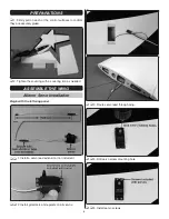
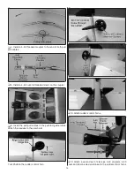
Page 6: ...en the covering with a covering iron as needed ASSEMBLE THE WING Aileron Servo Installation Begin with the left wing panel 1 Install a servo lead extension not included 2 Install grommets and eyelets...

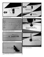
Page 7: ...7 6 Install servo horn 7 Aileron pushrod components 8 Install the 4 40 threaded clevis 9 Attach clevis to control horn 10 Position control horn on aileron 11 Mount control horn...

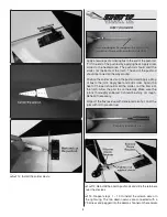
Page 8: ...o the joint Apply heat and add solder Again the heat of the part should melt the solder not the flame of the torch Allow the part to cool naturally Make sure the joint is thoroughly soldered It should...

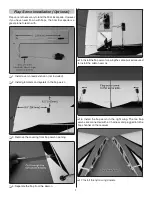
Page 9: ...not included 2 Install grommets and eyelets in the flap servo 3 Remove the covering from flap servo opening 4 Separate the flap from the aileron 5 Install the flap servo following the same procedure u...

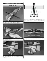
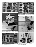
Page 10: ...rily install the horizontal stabilizer and the vertical fin A A A A 5 Check the alignment of the horizontal stabilizer The distance from the center of the nose of the fuselage to the tips of the horiz...

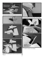
Page 11: ...0 minute epoxy to glue the stabilizer in the fuselage 7 Use 30 minute epoxy to glue the vertical fin in the fuselage 8 Glue the filler blocks on both sides of the fuselage 9 Attach the tail gear to th...

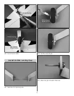
Page 12: ...12 10 Install the tail wheel Install the Main Landing Gear 1 Install the 3 16 4 8mm axles 2 Cut the axle to length 3 File a flat spot at the end of the axle...

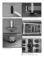
Page 13: ...he main landing gear on the fuselage Install the Rudder and Elevator Servos 1 Install the rudder servo and plug it into the receiver Temporarily plug the receiver battery into the receiver 2 Install t...

Page 14: ...aded clevis on the coupler 6 Insert the pull pull cables in the pushrod guide tubes Attach the clevises to the servo arm 7 Position the rudder control horn 8 Attach rudder control horns 9 Attach a sec...

Page 15: ...the rudder control horns 11 Install the elevator pushrods 12 Install the elevator servos Join the two servo leads with a Y harness and plug the Y harness into the receiver 13 Install the elevator cont...

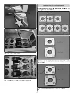
Page 16: ...to the elevator pushrods Electric Motor Installation Proceed to Engine and Tank Installation page 19 if a gas engine will be installed 1 Use epoxy to glue the front and back plates of the motor box to...

Page 17: ...t pieces of triangle stock between the front plate and the sides and the back plate and the sides Then glue the fourth side on 5 Drill the firewall 6 Open the cooling hole 7 Attach the motor box to th...

Page 18: ...o the ESC 14 Make two straps from the remaining hook and loop material Install the receiver reciever switch and receiver battery 15 Plug the ESC into the receiver Check that the throttle is set to rev...

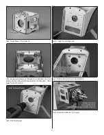
Page 19: ...pushrod locations on the firewall 5 Drill the firewall for the throttle choke and fuel line 6 Make three straps from the supplied hook and loop material 7 Install the straps on the fuel tank tray 8 In...

Page 20: ...assemble the throttle choke servo tray 14 Glue the tray in the fuselage 15 Install the throttle and choke servos and plug them into the receiver 16 Make two straps from the remaining hook and loop ma...

Page 21: ...the 2 56x1 threaded rod to the choke pushrod It is easier to remove the pushrod from the choke to install the threaded rod 22 Cut the outer pushrod tube 23 Roughen the outer pushrod with sandpaper 24...

Page 22: ...etely stopping the engine Assemble the Fuel Tank 1 Clean both ends of the brass tubes with sandpaper 2 Solder fuel line barbs onto one end of the brass tubes 3 Insert the brass tubes in the fuel tank...

Page 23: ...de the aluminum ring over the fuel tank neck 9 Secure the fuel tank stopper in the fuel tank Mark the top of the tank Install the Fuel Tank 1 Install and mark the fuel lines Vent Carb and Fill 2 Secur...

Page 24: ...rm water about 1 2 teaspoon of soap per gallon of water Submerse one of the decals in the solution and peel off the paper backing NOTE Even though the decals have a sticky back and are not the water t...

Page 25: ...E 2 3 Make certain that the control surfaces and the carburetor respond in the correct direction as shown in the diagram If any of the controls respond in the wrong direction use the servo reversing i...

Page 26: ...7 8 22mm 13 Down 5 8 16mm 9 Up 5 8 16mm 9 Down 3 4 19mm 17 Up 3 4 19mm 17 Down 1 2 13mm 12 Up 1 2 13mm 12 Down 7 8 22mm 20 Down 2 51mm 19 Right 2 51mm 19 Left 1 3 4 44mm 17 Right 1 3 4 44mm 17 Left R...

Page 27: ...6 113mm 1 Mark the C G range 2 With the plane ready to fly with an empty fuel tank or motor batteries installed use a Great Planes C G Machine or apply narrow 1 16 2mm strips of tape at the front and...

Page 28: ...lasses when starting or running engines Use a chicken stick or electric starter to start the engine If you do flip the propeller with your fingers wear a heavy leather glove such as a welder s glove W...

Page 29: ...or curved line s must be established in front of which all flying takes place with the other side for spectators Only personnel involved with flying the aircraft are allowed at or in the front of the...

Page 30: ...anding Landing The Escapade MX 30cc lands similar to a 60 size sport plane It does not require flaps to land but the flaps will allow the plane to land slower and is great practice for the pilot that...

Page 31: ...1 3 4 44mm 17 2 51mm 19 Up Down AILERON 3 4 19mm 17 1 2 13mm 12 Down FLAP 7 8 22mm 20 5 8 8mm elevator mixed with flap C G Forward 4 7 16 113mm from leading edge Aft 5 1 8 130mm from leading edge MOT...

Page 32: ......

Reviews: