background image

WARRANTY

Great Planes

®

Model Manufacturing Co. guarantees this kit to be free from defects in both material and workmanship at the date of

purchase. This warranty does not cover any component parts damaged by use or modification. In no case shall Great Planes’ liability
exceed the original cost of the purchased kit. 
Further, Great Planes reserves the right to change or modify this warranty without notice.

In that Great Planes has no control over the final assembly or material used for final assembly, no liability shall be assumed nor accepted
for any damage resulting from the use by the user of the final user-assembled product. By the act of using the user-assembled product,
the user accepts all resulting liability.

If the buyer is not prepared to accept the liability associated with the use of this product, the buyer is advised to return this kit
immediately in new and unused condition to the place of purchase.

To make a warranty claim send the defective part or item to Hobby Services at the address below:

Hobby Services

3002 N. Apollo Dr., Suite 1

Champaign, IL 61822 USA

Include a letter stating your name, return shipping address, as much contact information as possible (daytime telephone number, fax
number, e-mail address), a detailed description of the problem and a photocopy of the purchase receipt. Upon receipt of the package the
problem will be evaluated as quickly as possible.

READ THROUGH THIS MANUAL BEFORE STARTING
CONSTRUCTION. IT CONTAINS IMPORTANT WARNINGS
AND INSTRUCTIONS CONCERNING THE ASSEMBLY
AND USE OF THIS MODEL.

GPMZ0173 for GPMA1114  V1.0

© Copyright 2005

Champaign, Illinois

(217) 398-8970, Ext 5

airsupport@greatplanes.com

Wingspan: 35.5 in [915mm] 
Length: 29.5 in [750mm]
Weight: 7.5 – 9 oz [215 – 255 g]
Wing Area: 207 sq in [13 dm

2

]

Wing Loading: 4.5 – 5.8 oz/sq ft [15 – 18 g/dm

2

Radio: 4-channel w/3 micro servos and 10-Amp ESC
Power System: Included ElectriFly T-370 ferrite motor with gearbox, or optional direct-drive RimFire Brushless motor.

By Great Planes

INSTRUCTION MANUAL

Summary of Contents for Extra 300S ARF

Page 1: ...to the place of purchase To make a warranty claim send the defective part or item to Hobby Services at the address below Hobby Services 3002 N Apollo Dr Suite 1 Champaign IL 61822 USA Include a lette...

Page 2: ...to the FlatOuts Extra 300S ARF visit the Great Planes web site at www greatplanes com Open the Airplanes link then select the FlatOuts Extra 300S ARF If there is new technical information or changes...

Page 3: ...sic 3 D maneuvers However some advanced pilots who are already familiar with handling flat foamies may prefer to fly the Extra 300S with a computer radio capable of endpoint adjustments for fine tunin...

Page 4: ...st assured the FlatOuts Extra 300S is capable of 3 D flight with the included ElectriFly stick mount motor and gearbox combination But for pilots who always insist on upgrading and don t mind spending...

Page 5: ...Photographed 3mm Plywood Firewall Hook Loop Mounting Material O Rings 2 Gearbox Motor Block Plastic Tree Parts A1 Z Bend Clevis 10 A2 Offset Z Bend Clevis 4 B1 Stand Alone Control Horn 5 B2 Stand Alo...

Page 6: ...e 800 637 6050 Parts may also be ordered directly from Hobby Services by calling 217 398 0007 or via facsimile at 217 398 7721 but full retail prices and shipping and handling charges will apply Illin...

Page 7: ...tom of the hinge remain flush with the top and bottom of the control surface you are hinging IMPORTANT Avoid getting any CA on the tube or the arms of the clips The clips must rotate freely on the tub...

Page 8: ...ator D Once the glue has cured remove the tape 6 Cut the elevator halves free of the sheet 7 Join the elevators to the stab by snapping the clip hinges to the joiner tube 8 Insert an A1 Z bend clevis...

Page 9: ...w on this assembly will be referred to as the fuselage tube 3 Slide an E2 fuselage joiner two F3 fuselage servo mounts and another fuselage joiner onto the fuselage tube With the tube doubler forward...

Page 10: ...previous Expert Tip glue three C2 clip hinges and a C1 clip hinge control horn to the rudder using the 3 x 118mm 1 8 x 4 5 8 rudder post tube as a guide 10 Remove the rudder post tube from the rudder...

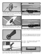
Page 11: ...mount and glue the servo mount into the precut opening in the wing Slide the wing into the slot in the bottom of the vertical fuselage Center the wing using the notches in the LE and TE as a guide Onc...

Page 12: ...arallel with the stab and horizontal fuselage and perpendicular to the vertical fuselage Once you are satisfied with alignment secure the landing gear legs with a drop of glue on both sides of each jo...

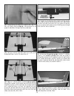
Page 13: ...to the rudder and not to the rudder post The bracket needs to pivot on the rudder post 1 Glue the elevator servo into the front servo mount in the left side of the fuselage The output shaft should be...

Page 14: ...of the clevis where it pivots in the arm or horn 8 Select two single sided servo arms to fit the elevator and rudder servos you are using Insert an A1 Z bend clevis into the outer hole of each arm Use...

Page 15: ...s in this section If you are installing a firewall mounted system proceed to Firewall Mounted Motor Systems on page 16 1 The 10 x 10 x 22mm hardwood motor mount block must be mounted in the correct or...

Page 16: ...s included in the propeller packaging into the rear of the propeller hub 7 Secure the prop to the prop saver with one of the included O rings 8 Connect your speed control to the motor and receiver Mou...

Page 17: ...firewall should be mounted so that the thrustline is offset 9mm below the center of the fuselage tube 5 Mount the motor to the firewall using the hardware supplied with your motor 6 Mount a propeller...

Page 18: ...ste but helps many pilots balance the extreme throws needed for 3 D flying with the need to make small corrections when in normal flight We recommend setting up your airplane according to the followin...

Page 19: ...to combust violently Ground check the operational range of your radio before the first flight of the day With the transmitter antenna collapsed and the receiver and transmitter on you should be able t...

Page 20: ...other side for spectators Only personnel involved with flying the aircraft are allowed at or in the front of the flight line Intentional flying behind the flight line is prohibited 4 I will operate my...

Page 21: ...e tail comes up gently apply up elevator to break ground and climb out Full throttle takeoffs are necessary only for extremely short runways When flying a 3 D aerobat like the Extra 300S ARF there are...

Page 22: ...______________ Where Purchased _________________________ Date Construction Started __________________ Date Construction Finished _________________ Finished Weight __________________________ Date of Fi...

Page 23: ...cycle and constantly display battery capacity voltage current and time as each cycle progresses Then imagine that the charger which can do all this is about the size of a thick paperback book and wei...

Page 24: ...Po park flyer batteries or peak charge 1 8 cell NiCd or NiMH radio packs Auto trickle for NiCds and NiMH packs is automatically set based on the fast charge rate Hook up the pack press the start butto...

Reviews: