background image

19

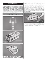
magnets in the cowl ring. As you did with the cowl ring, apply a 
light skin coating of thin CA over the magnets after they have 
been glued into the fuse. Let the CA cure without accelerator.

❏ 

4. Connect the cowl ring onto the fuse. Slide the cowl over 

the cowl ring and onto the fuse. Confi rm that the spinner 
backplate properly fi ts your motor shaft. If not, ream or drill 
it to the correct diameter. Temporarily install the spinner 
backplate onto the prop shaft. Adjust the position of the 
cowl on the fuse so that the colors line up with the covering 
on the fuse. The spinner backplate should be centered 
over the front cowl opening, and the backplate should be 
approximately 3/32" [2.4mm] beyond the front of the cowl. 
When satisfi ed, tack glue the cowl to the cowl ring in three or 
four spots by reaching through the front opening in the cowl. 
A CA applicator tip is very useful in this step. If you do not 
have an applicator tip long enough, use a stick to apply a dot 
of epoxy to each of the four cowl ring corners.

❏ 

5. Carefully remove the cowl (and cowl ring) from the fuse 

and apply a fi llet of medium or thick CA glue along the front 
of the cowl ring where it touches the cowl.

❏ 

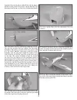
6. Cut a cooling hole out of the underside of the cowl 

as shown.

❏ 

7. Reattach the cowl to the fuse. Install the propeller, prop 

washer, and prop nut onto the prop shaft. Install the spinner 
cone using the included spinner screws.

❏ 

8. If you plan to install the instrument panel decal, do so 

now. Finish up the assembly by taping the canopy in position. 
Clear tape works well for this. 

Summary of Contents for Extra 330S ARF

Page 1: ...l assembly or material used for final assembly no liability shall be assumed nor accepted for any damage resulting from the use by the user of the final user assembled product By the act of using the...

Page 2: ...0S EP ARF visit the Great Planes web site at www greatplanes com Open the Airplanes link then select the Extra 330S EP ARF If there is new technical information or changes to this model a tech notice...

Page 3: ...ry Failure to follow all instructions could cause permanent damage to the battery and its surroundings and cause bodily harm ONLY use a LiPo approved charger NEVER use a NiCd NiMH peak charger NEVER c...

Page 4: ...rs Charger Note A cell balancer is required for the LiPo battery packs listed above Great Planes ElectriFly Equinox LiPo 1 to 5 Cell Balancer GPMM3160 A suitable charger is also required The Great Pla...

Page 5: ...vice can be provided by your hobby dealer or mail order company To locate a hobby dealer visit the Hobbico web site at www hobbico com Choose Where to Buy at the bottom of the menu on the left side of...

Page 6: ...ents list Great Planes Product Support 3002 N Apollo Drive Suite 1 Champaign IL 61822 Telephone 217 398 8970 ext 5 Fax 217 398 7721 E mail airsupport greatplanes com Kit Contents 1 Cowl 2 Fuse 3 Canop...

Page 7: ...nife 2 Insert the CA hinges halfway into the slots in the wing panels Push small T pins through the middle of the hinges to keep them centered Insert the ailerons onto the other ends of the hinges Ali...

Page 8: ...as cured confirm that the servos are properly secured to the wings and reinforce with extra glue if necessary 7 Locate two double sided servo arms that fit the output splines of your aileron servos an...

Page 9: ...m into the slots 12 Use the position of the control horn to adjust the length of the pushrods as needed Remove the servo arms from the aileron servos Connect the other adjustable clevises on the ailer...

Page 10: ...eath the second from the outside wing ribs The fuse must lay flat on its bottom side as shown These jigs will ensure that the wings are glued straight in the fuse Use a weight to hold the fuse down ag...

Page 11: ...the faster it must travel to melt a fine cut Peel off the covering 2 Wipe away the lines you drew and glue the fin into place 3 Trim the covering from the LE of each elevator half between the holes f...

Page 12: ...joiner wire with sandpaper and clean it off with alcohol Prepare the elevators by inserting a CA hinge into each hinge slot Use T pins to keep the hinges centered Put a light coating of epoxy onto the...

Page 13: ...cut off the arm that isn t used Attach an adjustable clevis to the outer holes of the arm and to the rudder control horn Attach the arm to the servo with the servo arm screw Install a 6 3 4 170mm pus...

Page 14: ...wheel pant and landing gear leg will help prevent the wheel pant from rotating on the axle Apply thread locking compound onto the screw and nut to secure the wheel assembly Repeat this step for the ot...

Page 15: ...ox using the screws included with the gearbox be sure to read the instructions included with the gearbox Remove the brass collar on the gearbox shaft and attach the motor mounting box front piece to t...

Page 16: ...are installed on the correct side as shown Assemble the box as shown with medium CA glue the longer side piece being on the left of the box 2 Use medium CA or epoxy to thoroughly glue the motor mounti...

Page 17: ...of the fuse Use clear tape to hold the antenna in place For a cleaner look run the receiver antenna through the inside of the fuse to the tail The antenna exits from a small hole drilled in the locat...

Page 18: ...ith the correct polarity facing out The magnets in the fuse must be attracted to the magnets in the battery hatch 8 Test fit the battery hatch onto the fuse INSTALL THE COWL CANOPY SPINNER 1 Prepare t...

Page 19: ...3 32 2 4mm beyond the front of the cowl When satisfied tack glue the cowl to the cowl ring in three or four spots by reaching through the front opening in the cowl A CA applicator tip is very useful...

Page 20: ...nd in the correct direction as shown in the diagram If any of the controls respond in the wrong direction use the servo reversing in the transmitter to reverse the servos connected to those controls B...

Page 21: ...3 If the tail drops the model is tail heavy and the battery pack and or receiver must be shifted to balance If the nose drops the model is nose heavy and the battery pack and or receiver must be shif...

Page 22: ...a damaged receiver crystal from a previous crash MOTOR SAFETY PRECAUTIONS Failure to follow these safety precautions may result in severe injury to yourself and others Get help from an experienced pi...

Page 23: ...at shrink tubing or special clips suitable for that purpose 10 Balance your propeller and spare propellers 11 Tighten the propeller nut and spinner 12 Placeyourname address AMAnumberandtelephone numbe...

Page 24: ...f you are going to overshoot smoothly advance the throttle always ready on the right rudder to counteract torque and climb out to make another attempt When you re ready to make your landing flare and...

Page 25: ...e Edge to the right Note that you may need to use some positive elevator and or left aileron to stop the Tumble at exactly Knife Edge This maneuver is easier to the right because torque helps stop the...

Page 26: ...Edge Loop and flying out Knife Edge When done correctly the plane pivots around the wing tip in a very small area This maneuver can be done either direction OTHER ITEMS AVAILABLE FROM GREAT PLANES Gre...

Page 27: ...re motors feature better cooling which means 50 more power than similar sized out runners Bearings are double shielded and because they are no comms or brushes to worry about RimFire motors are super...

Page 28: ...___ Where Purchased ____________________________ Date Construction Started _____________________ Date Construction Finished _______________________ Finished Weight _______________________________ Date...

Reviews: