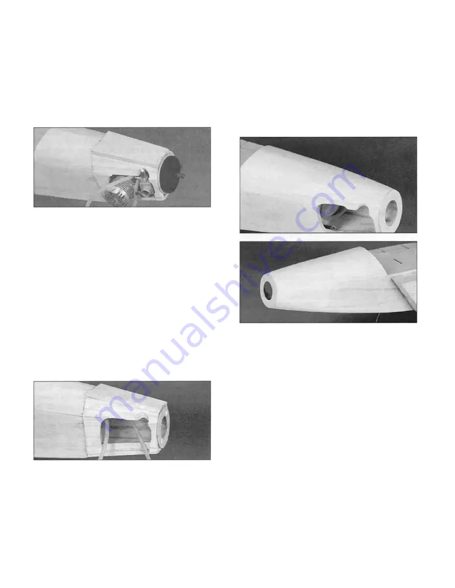
Trim the right piece to fit around the needle valve.
After the glue is cured, sand the top edges to a
bevel so the remaining nose top will fit in the next
step. You may need to remove the needle valve
before sanding the top edge. If you do, stuff the
needle valve opening with a piece of paper towel
to keep the dust out.
D 12. Remove the engine, mount and the throttle
cable again. As you have probably noticed, the
nose sides and top are going to get quite thin in
several places when the nose is carved to shape.
Add " Bondo" or another filler to the inside of the
engine compartment to build up these thin areas.
Apply polyester resin (or epoxy thinned with
alcohol) to the entire engine compartment to fuel
proof it.
D 8. Sand the remaining 1/4" balsa shaped
nose top to fit and glue it in place. Cut the spinner
backplate loose from the spinner ring and remove
it.
D 9. Carefully cut enough of the nose away so
you can remove the screws holding the engine in
place. Unhook the throttle clevis and try to remove
the engine You will probably have to cut away
some of the nose right top side before you can
remove the engine. Also remove the engine
mount.
D 13. Using a razor plane and a sanding block,
rough sand the nose section to a smooth cross
section as shown in the photo. The nose should
be round at the s p i n n e r ring and smoothly
transition to the cross sections shown on the plans
at the firewall and F2. Fill any voids with Hobbylite
or other wood filler Note- The spinner ring is
approximately 1/16" larger in diameter than most
2-1/4" diameter spinners to allow room for final
sanding. Make sure to sand the nose section to
blend smoothly with your spinner.
D 10. Cut two pieces of 1/2" balsa triangle
(WSTR014) to fit in the bottom comers of the nose
and glue them inside the bottom corners as shown
in the photo.
INSTALL THE RECEIVER BATTERY
D 11. Re-install the engine, mount and throttle
cable to make sure you can easily get the engine
in and out. If not, carve more wood away until you
can.
D 1. The receiver battery should normally be
installed in the aft portion of the servo
compartment to help balance the plane. It may be
necessary to move it forward later if the plane is
tail heavy but we suggest you go ahead and install
it there now.
23
Summary of Contents for F-15 EAGLE
Page 7: ...6 DIE CUT PATTERNS ...
Page 53: ...TWO VIEW DIAGRAM ...


