background image

12

❏ 

3. Cut the remaining adhesive-backed hook and loop 

fastener to fi t the receiver. Apply the receiver inside the fuselage. 
Orient the antenna according to the receiver's instructions.

❏ 

4. Plug the servo leads, aileron “Y” harness and the speed 

control into the appropriate channels in the receiver.

❏ 

5. Test run the motor to be sure the propeller is turning in 

the correct direction.

Install the Cowl

❏ 

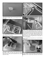
1. There is a small plywood plate inside the fuselage for the 

cowl mounting screws. The photo illustrates the approximate 
position of the plywood plates.

❏ 

2. From the center of the plywood plate draw a line back 

1" [ 25 mm] with a felt tip pen.

❏ 

3. Slide the cowl onto the fuselage. Slide the spinner back 

plate onto the motor shaft. Depending on your brand of motor 

you may need to enlarge the hole in the back plate. When the 

cowl is properly positioned the distance between the spinner 
back plate and the front of the cowl should be 3/32" [ 2.4 mm].

❏ 

4. Using the lines you put on the fuselage as a reference, 

drill a 1/16" [1.6 mm ] hole through the cowl and into the 
plywood plate in the fuselage. Secure the cowl with four 3/32" 

 5/16" [2.5 

 8 mm] washer head screws.

❏ 

5. Do not install the propeller at this time. For safety, this 

will be done after the plane is completed

.

Summary of Contents for FACTOR 3D

Page 1: ...assembled product the user accepts all resulting liability If the buyer is not prepared to accept the liability associated with the use of this product the buyer is advised to return this kit immedia...

Page 2: ...p www modelaircraft org IMPORTANT Two of the most important things you can do to preserve the radio controlled aircraft hobby are to avoid flying near full scale aircraft and avoid flying near or over...

Page 3: ...ty of your finished model depends on how you build it therefore we cannot in any way guarantee the performance of your completed model and no representa tions are expressed or implied as to the perfor...

Page 4: ...dation We recommend 30 minute epoxy only because you will need the working time or the additional strength Photos and sketches are placed before the step they refer to Frequently you can study photos...

Page 5: ...970 Order No Description Fuselage Wing Set Tail Surface Set Canopy Hatch Cowl Landing Gear Wheel Pants Spinner Tail Wheel Wire Wing Bolts Wing Tube Decal Sheet GPMA2100 GPMA2101 GPMA2102 GPMA2103 GPMA...

Page 6: ...the servo lead Pull the string and the servo lead through the wing Untie the string from the lead 2 Install the servo into the servo opening Drill a 1 16 1 6mm hole though the servo mount into the woo...

Page 7: ...of the pin should extend from the root rib 9 Repeat steps 1 8 for the left wing panel ASSEMBLE THE FUSELAGE Install the Main Landing Gear 1 Attach the two main landing gear legs to the fuselage with f...

Page 8: ...ng holes of the servo into the servo mounting rails in the fuselage 5 Install and then remove a servo mounting screw into each of the holes Apply a drop of thin CA into the holes to harden the threads...

Page 9: ...ng iron to cut the covering from the stab The tip of the soldering iron doesn t have to be sharp but a fine tip does work best Allow the iron to heat fully Use a straightedge to guide the soldering ir...

Page 10: ...control horn Place the control horn in line with the elevator servo arm Position the horn on the elevator the same as was done with the ailerons Mark the location of the mounting holes onto the ailero...

Page 11: ...l the motor to the firewall with four 4 40 3 8 3 10 mm machine screws 4 3mm lock washers and 4 3 mm flat washers Be sure to apply a drop of thread locker to the threads on each screw 2 Cut a piece of...

Page 12: ...ion of the plywood plates 2 From the center of the plywood plate draw a line back 1 25 mm with a felt tip pen 3 Slide the cowl onto the fuselage Slide the spinner back plate onto the motor shaft Depen...

Page 13: ...ther nylon stop nut onto the end of the screw to secure the wheel 3 Set the position of the wheel pants and secure the pant to the landing gear with a 1 16 1 4 1 6 6 mm wood screw Do this for both whe...

Page 14: ...ater allows accurate positioning and reduces air bubbles underneath 2 Position decals on the model Holding the decal down use a paper towel to wipe most of the water away 3 Use a piece of soft balsa o...

Page 15: ...loop material to hold the battery in position Do not connect the battery to the ESC while balancing the model 2 Install the propeller and spinner to the motor shaft Balance the Model C G More than an...

Page 16: ...ries Follow the battery charging instructions that came with your radio control system to charge the batteries You should always charge your transmitter batteries the night before you go flying and at...

Page 17: ...frequency sharing agreement listed in the complete AMA Safety Code 9 Under no circumstances may a pilot or other person touch a powered model in flight nor should any part of the model other than the...

Page 18: ...his moment it is likely that you will need to apply more right rudder to counteract motor torque Be smooth on the elevator stick allowing the model to establish a gentle climb to a safe altitude befor...

Page 19: ...gh or low rates This is not necessarily to improve your skills though it is never a bad idea but more importantly so you do not surprise yourself by impulsively attempting a maneuver and suddenly find...

Page 20: ...GPMA1552 Mnl Entire Contents 2013 Hobbico Inc All rights reserved...

Reviews: