background image

Note:

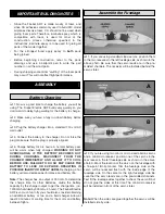
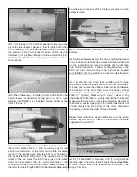
The motor is supplied with a flux ring installed. This

ring is present in the preceding photo and those that follow
and should be removed for the first flights. This ring will
increase flight time by reducing the current flow to the motor.
There is also a slight reduction in power.

3. Fit the 1/16" [2mm] ply reinforcement plates to the rear

of the fuselage. The plates are slightly oversize so that they
may be fitted to a variety of motors. Trim the plates as
needed to fit the shape of the fuselage.

4. Glue the reinforcement plates and the motor mount,

with the motor installed, into place with 6-minute epoxy.

The photo above shows the installation of a Kyosho AP-29
motor. As the motor is longer than the supplied motor, some
of the foam under the motor needs to be trimmed.

This photo shows the installation of a brushless motor and
speed control. Some trimming of the fuselage may be
needed, depending on the motor and speed controller.

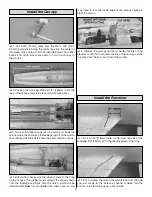
This photo used for the next two steps.

1. Find one of the 1" [25.4mm] pieces that you cut from

the aileron pushrod and glue it to the groove in the rear
hatch. If you can’t find one, a tooth pick can be used.

Final Assembly

13

Summary of Contents for Firebat

Page 1: ... final user assembled product By the act of using the user assembled product the user accepts all resulting liability If the buyer is not prepared to accept the liability associated with the use of this product the buyer is advised to return this kit immediately in new and unused condition to the place of purchase READ THROUGH THIS MANUAL BEFORE STARTING CONSTRUCTION IT CONTAINS IMPORTANT INSTRUCT...

Page 2: ...photos the written instructions are correct 3 You must use an R C radio system that is reliable and in good condition You must properly install all components so that the model operates correctly on the ground and in the air 4 You must check the operation of the model before every flight to insure that all equipment is operating and that the model has remained structurally sound Remember Take your...

Page 3: ...eceiver crystal FUTL62 for GPM low band FUTL63 for GPM high band FUTL47 for FUT low band FUTL48 for FUT high band HRCL23 for HRC desired channel Speed Control GPMM2010 C 10 12 amp GPMM2020 C 20 20 amp Servo Extension Wire 1 10 or 12 extension wire with standard receiver 1 18 or 24 extension wire with micro receiver Additionally an 8 cell 9 6 volt 600 to 1200 mAh battery pack is required GPMP0200 7...

Page 4: ...scription Qty 11 LEFT FUSELAGE 1 12 PROPELLERS 2 13 LEFT CANARD 1 14 MOTOR 1 15 MOTOR MOUNT PARTS BAG 1 Parts Deluxe Version not shown includes all parts shown above plus the following items BATTERY 1 ELECTRONIC SPEED CONTROLLER ESC 1 3 4 HOUR WALL CHARGER 1 8 9 10 11 12 13 14 15 1 2 3 4 5 6 7 PARTS LIST 3 6 152mm HARDWOOD STICKS 1 2 50mm BALSA BLOCK 1 2 50mm NYLON BOLT 2 NYLON WASHERS 1 LONG NYLO...

Page 5: ...ULTING IN POSSIBLE INJURY OR BODILY HARM Recharging a hot battery will also decrease performance and battery life Note The charger has an output of 300 mA To determine the charge time for other batteries divide the battery capacity by the charger output to get the charge time i e 1200 mAh divided by 300 mA 4 hours The Firebat Electric ARF is so much fun to fly you should also consider obtaining an...

Page 6: ...crap 1 16 1 6mm ply not included and glue it to the fuselage at the front of the servos The screws supplied with the servos or a dab of epoxy can be used to hold the servos in place See page 9 step 12 for another photo Note If you want to hold the servos in place with screws glue a piece of ply at the front and rear of the servos 6 Install a servo lead extension that will connect the electronic sp...

Page 7: ... 6 4 x 4 x 152mm hardwood stick If the control horns are loose secure them with a drop of CA glue or some epoxy Be sure to make a left and right torque rod as shown in the photo 3 Make a hole in each aileron to allow the control horn to come through from below the aileron The hardwood stick should seat squarely in the groove in the bottom of the aileron Trim the hardwood stick to length if needed ...

Page 8: ... as well 7 Cut a length of cellophane adhesive hinge tape the length of the aileron Stick the tape to the right aileron along the leading edge so that it is even with the bottom of the aileron Press the tape down firmly into place Fold the tape back over itself so that it will be easier to place it on the wing The tape in the above photo has been darkened so that it can be easily seen Note The ail...

Page 9: ...hows the installation of two mini servos 1 Glue the brass bearing tubes in place with 6 minute epoxy The longer bearing tube is glued to the right side of the fuselage The tubes should project about 1 32 1 mm past the sides of the fuselage Use the long canard joiner tube to align the bearing tubes as the epoxy hardens Be very careful not to get any epoxy on the joiner tube Hint Use a little vaseli...

Page 10: ... a straightedge to keep both canards aligned as shown in the above two photos Note For optimal flight performance it is very important that both canards be accurately aligned and move freely in the bearings 6 Connect one of the short pushrod wires with a Z bend to the elevator horn in the second hole from the center Connect another short pushrod wire to the servo arm also in the second hole from t...

Page 11: ...e rubber bands to the hook on the canopy The rubber bands will pull the canopy down onto the fuselage and back onto the hatch which will be installed later Note If you installed two aileron servos you may need to trim the inside edge of the canopy slightly to clear the servos 5 Remove the canopy and set it aside until later If the elevator control horn contacts the top of the canopy cut the top ho...

Page 12: ... earlier in the side of the fuselage 5 Secure the antenna in its channel with adhesive tape to cover it Make sure that the full length of the antenna is extended and that none of it remains inside the fuselage The motor supplied with the Firebat ARF has capacitors internally installed in the motor and is shown being installed in the following steps There are many other higher performance motors th...

Page 13: ...e shape of the fuselage 4 Glue the reinforcement plates and the motor mount with the motor installed into place with 6 minute epoxy The photo above shows the installation of a Kyosho AP 29 motor As the motor is longer than the supplied motor some of the foam under the motor needs to be trimmed This photo shows the installation of a brushless motor and speed control Some trimming of the fuselage ma...

Page 14: ... installation ready for the battery 6 Remove the screws from the servos holding the control arms in place and remove the arms as well Center the trims on the transmitter and move the throttle stick to idle then turn on the transmitter Connect a charged battery to the ESC and turn it on according to the instructions supplied with the ESC With the controls in neutral reinstall the servo control arms...

Page 15: ...e front of the model ahead of the C G not in the rear as is a normal elevator Therefore the canard TE must deflect down to obtain up elevator action 1 Turn on the transmitter and connect the battery to the speed control in the model Be certain the ailerons canards and motor respond as shown in the chart If required use the reversing function in the transmitter to reverse any controls so they respo...

Page 16: ...own you should always have your name address telephone number and AMA number on or inside your model It is required at all AMA R C club flying sites and AMA sanctioned flying events Fill out the identification tag on page 19 and place it on or inside your model Be certain the transmitter batteries are fully charged Follow the battery charging instructions that came with your radio control system t...

Page 17: ...not run the motor in an area of loose gravel or sand the propeller may throw such material in your face or eyes Keep your face and body as well as all spectators away from the path of the propeller as you start and run the motor Keep items such as these away from the prop loose clothing shirt sleeves ties scarfs long hair or loose objects pencils screwdrivers that may fall out of shirt or jacket p...

Page 18: ...y controlled operation of your model We recommend flying the Firebat ARF when the wind is no greater than ten miles per hour Less experienced flyers should fly the Firebat ARF only in calm less than one mile per hour conditions Frequently winds are calm in the early morning and early evening Often these are the most enjoyable times to fly anyway Until you have the Firebat ARF properly trimmed for ...

Page 19: ...e airplane with the runway or landing area Do not dive the airplane as it will pick up too much speed Instead allow the airplane to establish a gradual descent Concentrate on keeping it heading into the wind toward the runway When the plane reaches an altitude of about 3 feet 1 meter reduce power some more and gently and slowly apply a little up elevator to level the plane but be careful as too mu...

Page 20: ..._____________ Where Purchased _________________________ Date Construction Started __________________ Date Construction Finished _________________ Finished Weight __________________________ Date of First Flight ________________________ FLIGHT LOG ...

Reviews: