background image

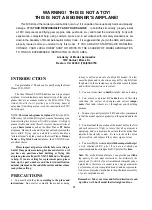
and any other imperfections. If possible, position each
spar so the imperfections (if any) are on the outer half of
the wing panel (toward the tip), where they will be least

affected by high stress. If the spars arc warped slightly, try
to "balance them out" by installing the warped spars in

opposite directions (see sketch). NOTICE: If you feel
that any of the wing parts arc unusable due to severe warps

or other defects, give us a call and we'll replace the parts.

T W O WARPED SPARS INSTALLED

THIS  W A Y WILL RESULT IN A

STRAIGHT WING

TWO  W A R P E D  S P A R S INSTALLED

THIS  W A Y WILL RESULT IN A

WARPED WING

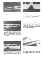
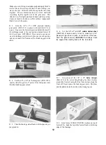
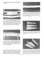
D 4. Find ihe four 1/8" x 3/8" x 14" balsa spar

doublers (FUN 1 W 17). Sand the last 2" one end of each
spar doubler to a taper as shown in the photo. Glue the spar

doublers to the spars with the square end of the spar
doubler lined up with the spar end. Sand the doubler to

match the spar and to remove any excess glue.

NOTE: Follow steps 6 through 13 to build the

LEFT wing panel, then repeat these steps to build

the RIGHT wing panel.

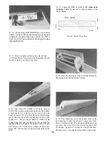
Work Surface

D D 6. Use some scrap pieces of 1/16" balsa to shim the

spar up off the work surface 1/16". Place a "shim" in every

other rib bay and pin a spar to the plan with the spar
doubler up and toward the root. NOTE:
 The spars are
cut slightly too long. Position the spar on the plan so ap-
proximately 1/8" extends past the center of the wing plan.

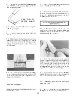
D D 7. Place the ribs on the spar with the jig tabs down,

in their approximate position, but do not glue. NOTE:

The wing is built upside down.

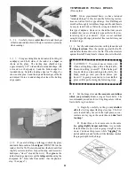
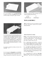
D 5. Carefully punch out all the die-cut 3/32" balsa

wing ribs. Sand the edges slightly to remove any die-
cutting irregularities. If you are going to build the wing on
a wing jig do not punch out the lightning holes yet as some

of them contain  t h e jig holes. You may even have to tack
glue these in place  u n t i l the wing is removed from the jig.
If you arc going to install individual servos for each

aileron, cut out me servo rail notches in ribs W4 and W5.
NOTE: If you are going to use only one servo now but
think you may want to have individual servos later, go

ahead and build the servo rails into the wing and cover

over them. Then they will be there if you decide you want
them. 17

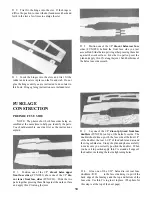
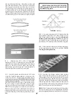
D D 8. Examine the shaped, notched balsa trailing

edges. Notice that the notches at one end of each TE arc
closer together. This is the "root" end of me TE. Insert all
ribs into the TE notches. The TE should rest on the ledges
on ribs W3, W6 and W 10 but make sure that it is also flush
with the tops of all ribs. Check to make sure that each rib
is perpendicular to the work surface and apply a drop of
thin CA to each joint on the TE and the spar.

NOTE: Thin CA glue may be used in tight-fitting joints,
but to insure strong joints we recommend that you follow
up by also applying medium or med/thick CA to all joints.

17

Summary of Contents for FUN-ONE

Page 1: ...the final assembly or material used for final assembly no liability shall be assumed nor accepted for any damage resulting from the use by the user of the final user assembled product By the act of u...

Page 2: ...Install Engine 27 Fit Fuel Tank and Fuelproof Tank Compartment 28 Mount Stabilizer and Fin 29 Install Canopy 30 Build the Wing Fairing 30 Shaping and Sanding 31 INSTALL PUSHRODS AND RADIO COMPONENTS...

Page 3: ...parts carefully before starting to build Ifany partsaremissing broken ordefective orif you have any questions about building or flying this airplane pleasecallusat 217 367 2069andwe llbeglad to help...

Page 4: ...have a radio without mixing capabilities you will normally install only one servo in the center of the wing NOTE If you arc going to use a high power 40 size engine you should consider using two ailer...

Page 5: ...5...

Page 6: ...g edgewith CA Use the plans as a reference to center the brace on the TE D 2 Remove all parts from the box As you do figure out the name of each part by comparing it with the plans and the parts list...

Page 7: ...en drill the final hole to a depth of 7 8 with a 9 64 drill bit The hole is drilled slightly oversize to allow for positioning and to create a hard epoxy sleeve around the wire D 6 Cut the ribs from t...

Page 8: ...ends Draw a centerline around the stab and sand the leading edge and the tips ofthe slab to a nice rounded cross section D 3 Cut the dorsal fin from the l 4 xl slick and tack glue it to the fin using...

Page 9: ...the fin and dorsal fin to a rounded shape but leave the trailing edge square CAUTION You must use extreme care when cutting hinge slots with an Xacto knife to avoid cutting yourself If the balsa part...

Page 10: ...y the parts You should assemble one side first as the instructions explain D 3 Lay one of the 1 8 die cut plywood front fuse doublers FUN1F06 on lop of the balsa fuse side The doubler should line up w...

Page 11: ...shouldcutofftheexcessboltlength 4 40 x 5 8 ASSEMBLE THE FUSELAGE D 1 Lay the two fuselage sides down flat on the work surface with the doublers facing up Trial fit formers Fl F2A F3 F4A B F5 and F6 fr...

Page 12: ...ch position and so you can switch from one style of landing gear to the other D 6 Cut the 1 8 x 3 x 6 1 2 middle bottom sheet FUN1F22 of balsa exactly in half to make two 3 1 4 pieces and glue them in...

Page 13: ...ove the tubes Scuff up the tube surface with 100 grit sandpaper in those locations and replace in the fuselage Glue the tubes in place with med thick CA D 12 If you want to install an antenna tube in...

Page 14: ...18 balsa stringers FUN1 F14 in place as shown in the photo The bottom stringer should start at the line you just drew on the stab bed and remain 1 16 away from the edge of the fuselage side to allow...

Page 15: ...t flush with the face of F4B D 21 Glue the 3 16 x 1 3 8 x 14 7 8 balsa turtle deck top FUN 1 Fl 5 in place making sure it is centered Cut off the ends and sand them flush with former F4T and the end o...

Page 16: ...atch and enlarge the holes in the hatch only 3 32 D 29 Use two 2 x 3 8 sheet metal screws SCRW024 and two 4 washers WSHR005 to screw the hatch into place Sand the sides and back of the hatch flush wit...

Page 17: ...so ap proximately 1 8 extendspast thecenterofthe wingplan D D 7 Place the ribs on the spar with thejig tabs down in their approximate position but do not glue NOTE The wing is built upside down D 5 C...

Page 18: ...6 and assemble the other wing panel D D 10 Position the 3 32 x 3 x 14 7 8 balsa shear web sheet FUN1W14 over the shear web template on the plan Make sure the sheet is correctly aligned with the templa...

Page 19: ...06 in place They easily should fit between the ribs and should not extend past the outer edges of the spars Hold or clamp them tightly against the spar while gluing them in place with epoxy D 6 Glue t...

Page 20: ...1 4 triangle BAL143 to each outside spar Wl ribjoint and a small piece at the trailing edge of each rib assembly See photo at step 11 D 11 Glue the two 1 8 ply W1A ribs FUN1W01 together and glue them...

Page 21: ...assem blies D 18 On the side of the wing with the dowels sticking out the bottom of the wing the leading edge should be cut away flush with the wing bolt plate between the W2 front ribs See bottom pho...

Page 22: ...traightnessby keeping the wing down on the flat surface D 1 Before applying the leading edge sheeting in the next step useyourT bartolightly sand off any protruding edgeson theshear webs andsmoothly b...

Page 23: ...he rails and tack glue them in place in the bottom of the notches with med thick CA Try to keep the servo as low in the wing as possible Be sure to allow enough space between the rails toget theservo...

Page 24: ...r sheets FUN1W12 to fit between the W3 ribs Positiononeofthesheetsbetweentheribsandmarkwhere thecenteroftheleadingedgesheet is Now slidethesheet forward until it touches the rear of the leading edge s...

Page 25: ...very docile when flying slowly enabling it to flare nose high for very slow landings however this may cause the plane to be a little sluggish when trying to enter a snap roll or spin Asharperleadinged...

Page 26: ...t of petroleum jelly to the ends of the plastic tubes to help prevent glue from getting inside and locking up the torque rods D 4 Drill a 7 64 hole in the ailerons at the torque rod locations starting...

Page 27: ...so that it is centered on this line and mark where the two outside holes should be drilled Drill a 9 64 hole at eachoutsidedot Theholes shouldbeperpendiculartothe landing gear plate D 1 Place the eng...

Page 28: ...th alcohol D 5 If you arc building it with tricycle landing gear install the nosegear WBNT075 and the nylon steering arm as shown in the sketch and on the plan Determine where thepushrod should exit t...

Page 29: ...center mark on the TE positioned over the joint between the two fuse sides D 5 Use a string and a T pin like you did on the wing but stick the pin at the front middleofthe turtle deck to help alignth...

Page 30: ...pieces should be 1 16 below the top of the hatch Glue the sides and the front pieces in place but be careful not to glue them to the fuselage D 3 Remove the wing from the fuselage and remove the wing...

Page 31: ...using a Z bend pliers or a standard pliers D 6 Remove the servo wheel from the servo and work the Z bends into the wheel NOTE You may have to enlarge the servo wheel holes with a 5 64 diameter drill...

Page 32: ...eron movement and page 36 for the correct direction of movement IMPORTANT D 10 Harden the balsa in the area of the control horns on both sides of all control surfaces by poking several holes with a pi...

Page 33: ...en set up the control surfaces to move at the low rate throws for sport flying and high rate throws for HOT DOGGING D 18 Securely anchor the pushrod guide lubes to F 4 using cross braces cut from scra...

Page 34: ...ling edges and the tip Modelers who do this often cut through the covering and part way into the balsa stab This can weaken the stab to the point where it may fail in flight Recommended Covering Seque...

Page 35: ...tubes to prevent glue from getting inside and locking them up epoxy Now carefully position the rudder with respect to the fin and glue the hinges with thin CA in the same manner as the elevator hinges...

Page 36: ...point at which your model should balance for your first flights Later you may wish to experiment by shifting the balance up to 1 4 forward or back to change the flying characteristics Moving the bala...

Page 37: ...ews remaintight thatthehingesaresecureandthatthepropis on tight RANGE CHECK YOUR RADIO Wherever you do fly you need tocheck theoperation oftheradiobeforeeverytimeyou fly Thismeanswiththe transmitteran...

Page 38: ...ng to avoid having models fly in the proximity of full scale aircraft 3 Where established I will abide by the safety rules for the flying site I use and I will not willfully and deliberately fly my mo...

Page 39: ...nt in flexible plastic pushrods Side play of pushrod in guide tube caused by tight bends Sloppy fit of Z bend in servo arm Insufficient glue used when gluing in the elevator joiner wire or aileron tor...

Page 40: ...bs 1A B D 2A Aligner Ply 1 32 DC Dihedral Braces SUB PACK LARGE BALSA SHEETS FUN1A02 FUN1F02 FUN1F04 2 1 Balsa 1 8 DC Rear Fuse Side Balsa 1 8 DC Rear Fuse Sheet SUB PACK HARDWARE FUN1M02 SUB PACK MED...

Reviews: