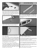
horn. If the control surface is not at neutral, unsnap the
clevis and adjust as needed.
❏ ❏
11. When done adjusting the clevis, tighten the 4-40
hex nut against the clevis. Be sure to use a drop of
Threadlocker to prevent the nut from backing off.
❏
12. Repeat steps 1 to 11 for the other elevator servo.
❏
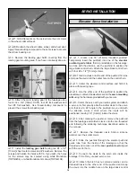
1. The rudder servo and pushrod installation is performed
following the same procedure as the elevators. The rudder
servo is located between the two elevator servos as shown. Be
sure that the rudder servo arm and the elevator servo arms do
not make contact and that the pushrods do not touch.
❏
2. Final installation will resemble the photo and sketch above.
Note: The firewall has been set up to accept the Fuji-Imvac
BT-43EI gas engine and as such the instructions have been
written to reflect this. 8-32 Blind nuts have been preinstalled
for your convenience for mounting the Fuji-Imvac engine. If
you choose to use another manufacturer’s gas engine within
our specified range, it is up to you as a modeler to
determine the best mounting method.
❏
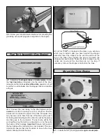
1. Using a felt-tip or Panel Line Pen, make a 1/4" [6.4mm]-
wide mark as shown in the photo.
Mount the Gas Engine
ENGINE INSTALLATION
Rudder Servo Installation
17


