background image

❏ ❏

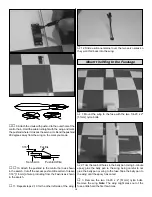
3. Pull the center of the string out of the servo hole in

the wing. It might take a little fishing to get it out. Take your
time. Use the string to pull the servo wire through the wing,
being careful to not pull the string loose from the other end
taped in the wing. Fit the servo in the wing.

❏ ❏

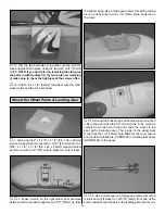
4. Drill 1/16" [1.6mm] holes through the servo mount

for the servo screws. Add a few drops of thin CA to the holes
and allow to fully harden. Mount the aileron servo using the
hardware that came with the servo.

❏ ❏

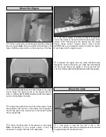
5. Make a mark on the bottom L.E. of the right aileron

12-1/2" [315mm] from the inboard end of the aileron.

❏ ❏

6. Center a control horn on the mark you made. Drill

two 1/16" [1.6mm] holes through the aileron for mounting the
control horn. Mount the control horn using the 2-56 x 3/4"
[19mm] socket head cap screws (SHCS) with the nylon
backing plate on the top-side of the aileron. Note: Turning a
2-56 tap through the back plate holes makes it easier to get
the SHCS to thread into them.

❏ ❏

7. Thread a clevis 25 turns onto the end of one 12"

[305mm] pushrod. Slip a silicone retainer over the pushrod
down to the clevis.

❏ ❏

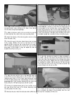
8. Make a one-arm servo arm by cutting three arms

off a four-arm servo arm. Enlarge the holes in the arm with
a Hobbico

®

Servo Horn Drill (or a #48 or 5/64" [2mm] drill bit)

so the pushrod will fit. Connect the servo lead to the
receiver. Turn on the transmitter and receiver to center the
servo. Place the servo arm on the servo so it is pointing
straight towards the wing tip.

Cut Off

Unused Arms

Enlarge to 5/64"

Correct

Incorrect

9

Summary of Contents for Giant U-Can-Do 3D

Page 1: ... By the act of using the user assembled product the user accepts all resulting liability If the buyer is not prepared to accept the liability associated with the use of this product the buyer is advised to return this kit immediately in new and unused condition to the place of purchase READ THROUGH THIS MANUAL BEFORE STARTING CONSTRUCTION IT CONTAINS IMPORTANT WARNINGS AND INSTRUCTIONS CONCERNING ...

Page 2: ...high torque 4 stroke such as an OS 91 the U CAN DO 3D provides exceptional slow speed and below stall speed 3D aerobatic performance For the latest technical updates or manual corrections to the U CAN DO 3D visit the web site listed below and select the Great Planes U CAN DO 3D ARF If there is new technical information or changes to this model a tech notice box will appear in the upper left corner...

Page 3: ...eses 4 channel radio with 6 standard sized servos as noted below Note that a 6 channel fully computerized radio system is highly recommended for maximum flexibility and performance Ailerons Two ball bearing servos 50 in oz HCAM0170 One 20 y harness HCAM2751 OR Two 6 extensions HCAM2701 and one y harness HCAM2500 Rudder One high torque servo 90 in oz HCAM0191 One 24 servo extension HCAM2200 Elevato...

Page 4: ...5 There are two types of screws used in this kit Sheet metal screws are designated by a number and a length For example 6 x 3 4 19mm This is a number six screw that is 3 4 19mm long Machine screws are designated by a number threads per inch and a length For example 4 40 x 3 4 19mm This is a number four screw that is 3 4 19mm long with forty threads per inch When you see the term test fit in the in...

Page 5: ... mount 4 8 32 x 1 socket head screws engine mount to firewall 8 8 flat washers mounting engine and engine mount 8 8 lock washers mounting engine and engine mount 4 5 32 wheel collar main wheels 4 6 32 x 1 8 socket head screw main wheels 6 2 56 x 1 2 socket head screw rudder elevator ailerons 4 2 56 x 3 4 socket head screw aileron control horns 1 Brass quick connect body throttle connection 1 Nylon...

Page 6: ... manual Contact Product Support Full size plans Not available Kit parts listed below Hobby Supplier GPMA2300 Wing Kit one piece wing ailerons dowels and hinge material GPMA2301 Fuselage Kit Fuse belly pan 2 balsa tank holders stab fillet 4 cowl mounting blocks and servo tray GPMA2302 Tail Set stab elevators fin rudder and hinge material GPMA2303 Landing Gear GPMA2304 Fiberglass Cowl GPMA2305 Canop...

Page 7: ...ering on the wing from A The servo wire hole in the top center of the wing B Both servo openings C Both dowel holes D Top and Bottom wing bolt holes 2 Use your sanding bar to round one end of each of the 5 16 x 1 3 4 8 x 70mm wing dowels Use epoxy to glue the two wing dowels into the wing with the non rounded end in the wing 3 Cut eight 3 4 x 1 19 x 25mm hinges from the 2 x 9 50 x 230mm CA hinge s...

Page 8: ...ges Adjust the ailerons so there is a small gap just enough to see light through or to slip a piece of paper through between the aileron and the wing 10 Apply six drops of thin CA to the top and bottom of each hinge Do not use CA accelerator After the CA has fully hardened test the hinges by pulling on the ailerons 1 Add servo extensions to the two aileron servos so that the total length of the le...

Page 9: ...16 1 6mm holes through the aileron for mounting the control horn Mount the control horn using the 2 56 x 3 4 19mm socket head cap screws SHCS with the nylon backing plate on the top side of the aileron Note Turning a 2 56 tap through the back plate holes makes it easier to get the SHCS to thread into them 7 Thread a clevis 25 turns onto the end of one 12 305mm pushrod Slip a silicone retainer over...

Page 10: ...teps 2 10 for the other left side of the wing 12 Slide a silicone retainer over the two servo wires so they won t fall back into the wing 1 Mount the wing to the fuse with the two 1 4 20 x 2 51mm nylon bolts 2 Trim the two bolt holes in the belly pan Using 6 minute epoxy glue the belly pan to the wing being careful to not glue the belly pan or wing to the fuse Tape the belly pan to the wing until ...

Page 11: ...ep the stab fillet in place 4 Use a 11 blade to remove the false fin from the fin slot Note It may be necessary to pry up slightly on the front of the fin fillet to remove it 5 Fit the fin in place and mark the covering on the fin where it contacts the fuse 6 Trim the covering 1 8 3mm below the lines you made on the fin Be very careful not to cut into the fin itself Wipe away the marks on the fin ...

Page 12: ... or a 5 32 4mm brass tube sharpened on the end to cut a groove in the leading edge of the rudder to accommodate the nylon tail gear bearing Drill a 1 8 3 2mm hole into the rudder for the arm portion of the tail gear wire 10 Carefully apply a small dab of petroleum jelly to the top and bottom of the tail gear bearing where the tail gear wire goes through the bearing to keep glue from entering Apply...

Page 13: ...ke a mark on the right wheel pant centered between the wheel pant supports and 1 2 13mm up from the bottom edge Use a high speed rotary tool with a cutting bit or a hobby knife to cut a 1 2 13mm hole centered on the mark 3 Round the bottom edge of the wheel pant mount so it fits in the pant when the 1 2 13mm hole in the mount is centered over the hole in the pant Glue the mount to the pant with 30...

Page 14: ...le and tighten the set screws 8 Drill two 1 16 1 6mm holes through the pant using the holes in the gear as a guide 9 Fasten the wheel pants to the landing gear with two 2 x 3 8 screws Remove the set screws in the wheel collars and add a drop of oil to the axle and the wheel Add a drop of threadlocker to the set screws install them into the wheel collars and securely tighten Note Double check that ...

Page 15: ...f the spinner on the engine Note Depending on your engine choice it may be necessary to enlarge the hole in the back plate 5 Use small clamps or another method to temporarily secure the engine to the mount with the back plate of the spinner 5 7 8 150mm from the firewall Use the Great Planes Dead Center Engine Mount Hole Locator GPMR8130 or your preferred method to mark the engine mount holes onto ...

Page 16: ... a 2 washer 7 With your assistant holding the cowl in position mark drill and mount the cowl to the three remaining cowl mounting blocks the same way 8 Remove the cowl Clean the reference marks off the fuse 9 Use the filler valve mount from a Great Planes Handy Mounts set GPMQ6000 or fashion a mount from 1 8 3mm plywood not included for the fuel filler valve A Great Planes Easy Fueler for glow fue...

Page 17: ...in the photo then insert them into the tank Tighten the screw to expand the stopper thus sealing the tank Be certain the fuel line weight clunk at the end of the fuel line inside the tank does not contact the rear of the tank Otherwise the line may become stuck above the fuel level and discontinue fuel flow Remember or use a felt tip pen to mark which tube is the fuel pick up tube and which tube i...

Page 18: ...en Mount the tail servos using the hardware that came with the servo 4 Make a mark on the bottom L E of each elevator 1 2 13mm from the inboard edge of each elevator Position the control horn centered over the mark Mark the hole locations on the elevator 5 Drill 1 16 1 6mm holes through the elevators for mounting the control horns with 2 56 x 1 2 SHCS socket head cap screws then mount the control ...

Page 19: ...ods to the control horns Hold the control surfaces straight and mark the pushrods where they cross the servo arms Bend the pushrods 90 degrees away from the fuse on the marks you made Turn the receiver and transmitter off 11 Attach the pushrods to the control horns as shown Trim the pushrod being certain to leave 1 16 1 6mm of wire protruding from the Faslinks 12 Screw a clevis 10 turns onto the e...

Page 20: ...through the bottom sheeting aft of the wing opening and routed the antenna through the hole The end of the antenna was connected to a hook made from a cut off servo arm connected to a small rubber band and the tail gear 1 Use curved tip scissors to cut out the canopy along the cut line True the edges by sanding with medium grit sandpaper 2 Place the canopy on the cockpit Use a fine point felt tip ...

Page 21: ...nd setting the throws at the low rate settings NOTE The throws are measured at the widest part of the elevators rudder and ailerons More than any other factor the C G balance point can have the greatest effect on how a model flies and may determine whether or not your first flight will be successful If you value this model and wish to enjoy it for many flights DO NOT OVERLOOK THIS IMPORTANT PROCED...

Page 22: ...he model by the engine propeller shaft and the bottom of the fuse under the TE of the fin Do this several times 2 If one wing always drops when you lift the model it means that side is heavy Balance the airplane by adding weight to the other wing tip An airplane that has been laterally balanced will track better in loops and other maneuvers No matter if you fly at an AMA sanctioned R C club site o...

Page 23: ...safe place away from high heat sparks or flames as fuel is very flammable Do not smoke near the engine or fuel and remember that engine exhaust gives off a great deal of deadly carbon monoxide Therefore do not run the engine in a closed room or garage Get help from an experienced pilot when learning to operate engines Use safety glasses when starting or running engines Do not run the engine in an ...

Page 24: ...e retainers on all the clevises and that all servo arms are secured to the servos with the screws included with your radio 12 Secure connections between servo wires and Y connectors or servo extensions and the connection between your battery pack and the on off switch with vinyl tape heat shrink tubing or special clips suitable for that purpose 13 Make sure any servo extension cords you may have u...

Page 25: ... but use this first flight to become familiar with your model before landing To initiate a landing approach lower the throttle while on the downwind leg Allow the nose of the model to pitch downward to gradually bleed off altitude Continue to lose altitude but maintain airspeed by keeping the nose down as you turn onto the crosswind leg Make your final turn toward the runway into the wind keeping ...

Page 26: ...RUQ1065 and True Turn lock nut TRUQ3063 Note A 2 1 4 nylon spinner is included with the U Can Do 3D but with the larger engines it requires extensive trimming of the spinner If you have to trim the spinner I strongly suggest using an aluminum spinner instead Elevators Futaba 9250 digital FUTM0220 Ailerons Futaba 9250 digital Rudder Futaba 9151 digital FUTM0211 Throttle Futaba 9001 FUTM0075 The lar...

Page 27: ...ctric powered boats Futaba s S9001 servo features a coreless motor that reduces weight for smoother faster response Dual bearings in the final gear speed transit time Comes with J connector one attached servo horn three extra servo horns and mounting hardware 1 year warranty Futaba S9001 Aircraft Coreless BB Servo FUTM0075 Length 1 59 in Width 0 78 in Height 1 42 in Weight 1 69 oz Torque 54 2 oz i...

Page 28: ..._____________ Where Purchased _________________________ Date Construction Started __________________ Date Construction Finished _________________ Finished Weight __________________________ Date of First Flight ________________________ FLIGHT LOG ...

Reviews: