❏ ❏
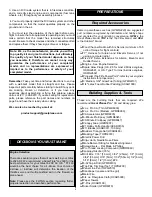
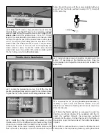
7. Thread a 4-40 hex nut and a 4-40 clevis onto the
threaded end of the pushrod wire. Attach the clevis to the
control horn.
❏ ❏
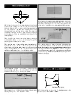
8. Use a felt-tip pen to mark the pushrod wire where it
crosses the holes in the aileron servo arm. Cut the pushrod
wire 3/4" [19mm] behind the mark.
❏ ❏
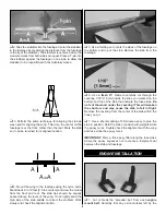
9. Locate a solder clevis. Use the following sequence
to solder the clevis to the pushrod:
❏ ❏
A. Lightly sand the pushrod and clean it with alcohol.
❏ ❏
B. Insert the pushrod into the non-threaded clevis. The
wire should protrude 1/16" [1.5mm] inside the forks of the
clevis.
❏ ❏
C. Apply a small amount of soldering flux to the joint.
❏ ❏
D. Apply heat evenly to the pushrod and the clevis and
then touch the solder to the joint and allow it to flow.
❏ ❏
E. Allow the pushrod and clevis to cool slowly before
continuing.
❏ ❏
10. Place a clevis retainer onto both of the clevises.
Attach the pushrod to the servo and control horn.
❏
11. Return to step 3 and connect the other elevator servo
to the other elevator the same way.
Note:
The procedure for installing the rudder to the fin is
similar to the installation of the elevators.
❏
1. Cut two 3/4" x 1" [ 19mm x 25mm] hinges from the CA
hinge strip supplied with this kit. Cut one 1-1/2" x 1" [38mm
x 25mm] hinges from the CA hinge strip supplied with this
kit. This larger hinge is used as the bottom hinge on the
rudder. The hinge is positioned vertically in the slot. Snip the
corners off so they go into the slots easier.
❏
2. Test fit the rudder to the fin. If the hinges are difficult to
install or don’t go in far enough, carefully enlarge the hinge
slots with a hobby knife and a #11 blade.
❏
3. Drill a 3/32" [2.5mm] hole, 1/2" [13mm] deep, in the
center of the hinge slot. Drill two evenly spaced holes for the
bottom hinge. If you use a Dremel MultiPro for this task, it
will result in a cleaner hole than if you use a slower speed
drill. Drilling the hole will twist some of the wood fibers into
the slot, making it difficult to insert the hinge, so you should
reinsert the knife blade, working it back and forth a few times
to clean out the slot.
❏
4. If the hinges don’t remain centered, remove the rudder
and insert a pin in the center of the hinges.
❏
5. Cut a paper towel into approximately 2" [50mm]
squares. Add six drops of thin CA to the center of the hinges
on both sides. Use the paper towel squares to absorb
excess CA from the hinge gap before it cures. Do not use
CA accelerator; allow the CA to cure slowly.
❏
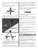
1. Locate the hole for the Rudder Servo and remove the
covering from the side of the fuselage using a sharp hobby
knife. Do not cut into the underlying wood, as this will
weaken the structure and could cause a failure in flight. Seal
down the edges with the Trim Seal Tool. Use 6-minute
epoxy to fuelproof any exposed wood.
❏
2. Install the rubber grommets and eyelets on your rudder
servo. Attach a servo extension to the rudder servo. Use
heat shrink tubing or electrical tape to secure the servo lead
to the extension so it doesn’t unplug in flight. Drop the
extension into the fuselage.
❏
3. Fit the rudder servo in the fuselage. Hold the servo to
the fuselage so the sides don’t contact the fuselage and drill
1/16" [1.5mm] holes for the servo mounting screws.
Remove the servo and wick a few drops of thin CA into each
of the four holes. Mount the servo to the fuselage with the
screws included with your servos.
❏
4. Cut the unused arms from one of your servo horns and
mount it to your rudder servo. The remaining arm faces the
bottom of the fuselage.
Install the Rudder Servo
Attach the Rudder
16


