16
❏
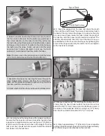
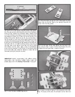
7. Drill 1/16" [1.6mm] holes at the marks you made. Thread
a 2mm x 8mm self-tapping screw into each hole and back it
out. Apply a couple drops of thin CA glue to each hole and
allow it to harden.
❏
8. Apply CA or epoxy to the nylon retainer and reinstall
the tail gear assembly into the bushing and rudder. Do not
glue the nylon retainer to the guide wire. The wire must slide
freely through the hole in the retainer. Gently tap the retainer
in place until approximately 3/16" [4.8mm] protrudes below
the bottom of the rudder. Attach the tail gear bracket using
two 2mm x 8mm self-tapping screws. Thread the 3mm set
screw into the tail gear collar with a drop of threadlocking
compound. Cut off the excess guide wire 1/2" [13mm] behind
the nylon retainer.
❏
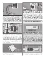
9. Confi rm that the tail wheel rotates freely. Oil the axle and
adjust the position of the 3mm wheel collar if necessary.
Install the Elevator Servos & Pushrods
❏
1. Trim the covering from the elevator servo bays leaving
1/8" [3mm] around the opening. Use a trim iron to seal down
the covering around the edges of the servo bays.
❏
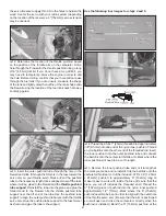
2. Attach a 36" [914mm] servo extension to each elevator
servo. Secure the servo extensions with the included heat-
shrink tubing. Feed the servo extensions through the fuse
and install the servos into the servo bays with the splines
facing forward using the mounting hardware included with
the servos. Be sure to harden the servo mounting screws
with thin CA.
❏
3. Attach a servo arm to each elevator servo
pointing downward.
❏
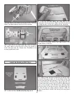
4. Just as you did with the ailerons, begin assembly of the
elevator pushrods using two .095" x 12" [2.4mm x 305mm]
pushrod wires threaded on one end, two 4-40 clevises and
two 4-40 nuts. Attach the clevis of each pushrod to the servo
arms and use the pushrod as a guide to position the control
horns onto the underside of the elevators. Secure the control
horns to the elevators with #4 x 5/8" [16mm] sheet metal
screws, being sure that you are drilling the screw holes
through the plywood plates in the elevators. Do not drill all
the way through the elevators! Center the elevators and use
a solder clevis to mark where to cut the pushrod wires. Cut
the wires, solder the clevises to the pushrods and attach the
pushrods to the elevators, securing the clevises with silicone
clevis retainers.
Note: The Sukhoi SU-31 1.60 ARF is setup for either forward
(pull-pull system) or aft (pushrod system) rudder servo
positions in order to offset ballast that may be required to
balance the airplane. The rudder servos will be installed
after the power system is put in place. After the installation
of the power system, the current C.G. of the plane can be
checked which will determine the optimum location of the
rudder servos.
Summary of Contents for GPMA1412
Page 52: ......


