22
❏
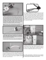
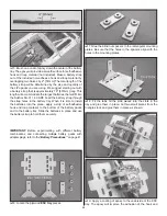
7. When satisfi ed with the pushrod shape and length,
remove the clevis from the pushrod and take the pushrod
out of the plane. Slide the outer pushrod tube through the
hole in the fi rewall. Mark and cut the pushrod tube to length.
Use sandpaper to scuff the pushrod where it will be glued
into the hole in the fi rewall. Reinstall the throttle pushrod into
the outer pushrod tube and thread the clevis back onto the
pushrod end. Put a silicone clevis retainer over the clevis
and connect the clevis to the throttle servo arm. Clip the
plywood pushrod tube support onto the outer pushrod
tube and glue it to the front of the second former as shown.
(If necessary, cut or sand the support shorter to fi t properly.)
Add a couple drops of glue where the support clips to the
tube to secure it in place.
GAS ENGINE INSTALLATION
Mount the Engine
A template is provided on page 51 for mounting the Fuji-Imvac
BT-43 EI-2 engine and pictures taken show the installation of
this model gas engine. If another model engine is used, the
engine manufacturer may provide a mounting template to
use on the fi rewall. The gas engine installation will be similar
for most model engines.
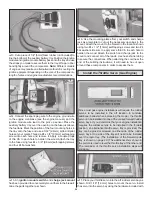
Because of the possibility of ignition engines creating
radio noise, we use a plastic pushrod for the throttle
servo installation. This isolates the engine and any radio
noise from the servos. This is an IMPORTANT selection,
and we cannot recommend strongly enough that you DO
NOT change this pushrod to a metal pushrod. All radio
equipment – including throttle servo, receiver battery,
electronic kill switch, receiver on/off switch, servo
leads – should be mounted at least 10" [254mm] away
from anything related to the ignition/gasoline engine.
Any material used between the engine and the radio
equipment is STRONGLY recommended to be plastic,
nylon, or otherwise non-metallic and nonconductive to
minimize ignition noise transmission.
❏
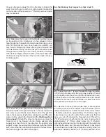
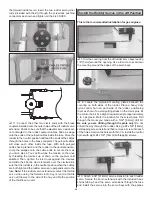
1. Cut the template out on page 51 for mounting the
Fuji-Imvac BT-43 EI-2 engine. Use tape or spray adhesive
to hold the template to the fi rewall. Align the vertical and
horizontal lines on the template with the embossed lines on
the fi rewall.
❏
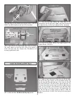
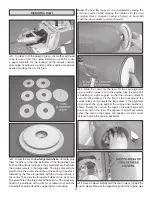
2. Use a large T-pin or a wire sharpened on the end to
transfer each bolt hole mark on the template into the fi rewall.
Summary of Contents for GPMA1412
Page 52: ......


