26
❏
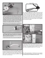
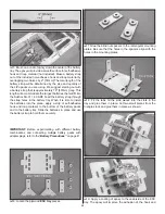
3. Cut a piece of 1/4" [6mm] foam rubber (not included) to
line the bottom of the auxiliary battery tray. Position the ignition
module and ignition module battery pack onto the tray and use
the straps you made to secure them to the tray. Wrap a rubber
band tightly around the components. Note: Different models
of engines may require an alternative method of mounting the
ignition equipment depending on the size of the components,
length of wires and engine manufacturer recommendations.
❏
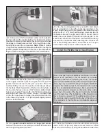
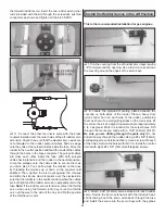
4. Connect the spark plug wire to the engine, ground wire
to the engine crankcase (see the engine manual), and the
ignition module wire lead to the pick up sensor. Place the
auxiliary battery tray over the opening on the fuse just above
the fuel tank. Mark the position of the four mounting holes in
the tray onto the fuse and use a 3/32" [2.4mm] bit to drill pilot
holes at your marks. Thread a #4 x 3/8" [9.5mm] self-tapping
screw into each hole and remove it. Apply a couple drops
of thin CA to each hole to harden the wood. Attach the tray
to the fuse using four #4 x 3/8" [9.5mm] self-tapping screws
and four #4 fl at washers.
❏
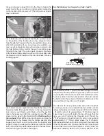
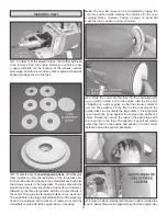
5. An ignition module switch and charge jack mount
has been provided to conveniently mount them to the fi rewall.
Glue the parts together as shown.
❏
6. Use the mounting plates from your switch and charge
jack as a template to cut out the necessary openings in the
mount. Attach the mount to the fi rewall in the location shown
using two #4 x 1/2" [13mm] self-tapping screws and two #4
fl at washers. Be sure to apply some thin CA to each hole to
harden the wood. Attach the switch and charge jack to the
mount and connect all of the leads. Use heat-shrink tubing
to secure the connections. When attaching the cowl near the
end of the building instructions, it will need to be cut open
around these components in order to access them.
Install the Throttle Servo (Gas Engine)
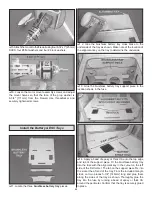
Since most gas engine installations will require the rudder
servos to be installed in the aft location to minimize
additional ballast when balancing the model, the throttle
servo can be installed into one of the unused forward rudder
servo bays. If you determine that your engine installation
requires the rudder servos to be installed in the forward
position, an alternative throttle servo tray is provided. The
tray can be glued or screwed on either side of the rudder
servo bays. One side of the tray will need to be installed
over the radio tray. (The installation of the forward radio
tray is shown on page 20.) The additional shim shown in
the picture is used to level the throttle tray at the other end.
The remainder of the throttle servo installation steps will
still apply.
❏
1. Place your throttle servo into the aft rudder servo bay as
shown. Drill 1/16" [1.6mm] holes to mount the servo. Install
the servo into the servo bay using the hardware included with
Summary of Contents for GPMA1412
Page 52: ......


