33
❏
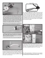
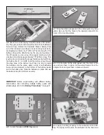
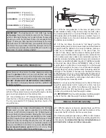
6. Feed the pull-pull cables through the slots in the fuse.
Be sure that the other ends make it through the fuse to
the rudder servos. Turning the airplane up on its nose and
feeding the cable ends into the fuse makes this task easier.
Connect the clevises on the cables to the outer holes in the
rudder control horns.
Use these images for steps 7 and 8
❏
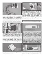
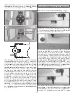
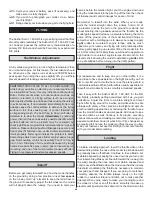
7. Two 3-7/8" [98mm] double aluminum servo arm
extensions are included for the rudder pull-pull system.
Locate the large servo wheels included with the rudder
servos (different model servos may come with servo wheels
that are larger or smaller than the ones shown in the picture.
The actual size of the servo wheels being used is not critical).
Fit the aluminum servo extensions to the undersides of the
servo wheels and tape them in place. Use a 1/16" [1.6mm]
drill bit to drill through the four mounting holes in the servo
extensions into the plastic servo wheels. Remove the servo
wheels from the extensions and enlarge the holes with a
3/32" [2.4mm] drill bit.
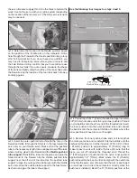
The next two images are used for steps 8 and 9
❏
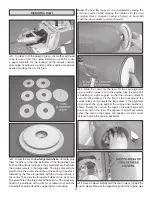
8. Using eight 2-56 x 3/8" [9.5mm] machine screws, eight
#2 fl at washers, and threadlocking compound, attach the
servo extensions to the servo wheels. With a cut-off wheel,
cut off the ends of the screws that protrude from underneath
the servo extensions.
❏
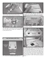
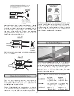
9. Drill out the inner holes of both servo extensions using a
7/64" [2.8mm] bit. Do not use any other size drill bit for this
step. Secure a heavy duty screw-lock pushrod connector to each
arm in the holes you just drilled out with a metal retainer. Using a
cut-off wheel, cut two 4-40 x 1/4" [6mm] SHCS to approximately
5/32" [4mm] long (cut off approximately three threads). Cutting
these screws will prevent the screw heads from contacting the
fuse former in front of the rudder servos. Loosely thread these
two 4-40 SHCS into the screw-lock pushrod connectors on one
of the servo arm extensions. Thread another two 4-40 x 1/4"
[6mm] SHCS (uncut) into the screw-lock pushrod connectors
on the other servo arm extension.
❏
10. With the servos centered using the radio and trims, align
the servo arms perpendicular with the fuse centerline and
parallel with each other and secure them to the rudder servos with
the servo arm screws. The servo arm extension that contains the
4-40 SHCS you cut down in step 8 should be installed on
Summary of Contents for GPMA1412
Page 52: ......


