35
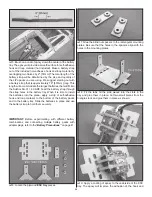
facing forward using the mounting hardware included with the
servos. Be sure to harden the servo mounting screws with
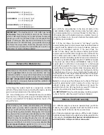
thin CA. Attach the servo arms pointing down as shown.
❏
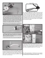
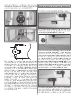
4. Assemble the rudder pushrods using two .095" x 12"
[2.4mm x 305mm] pushrod wires threaded on one end, two
4-40 clevises, two 4-40 nuts, two solder clevises, and four
silicone clevis retainers. Just as you did with the aileron and
elevator pushrods, mark and cut the pushrods to length,
solder the clevises to the pushrods, and attach the pushrods
to the elevators. Secure the clevises with silicone clevis
retainers. Be sure to use threadlocking compound on the
pushrod threads.
FINISH THE MODEL
Install the Radio System
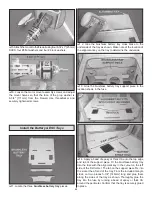
Note: There are multiple locations to install the receiver and
receiver battery pack depending on the power system being
used and the ballast needed to balance the airplane at the
recommended point. A plywood auxiliary battery tray is included
and can be secured to the top of the motor mounting box. A
forward and aft radio tray are also provided that will accommodate
both components. Read through the radio installation steps and
choose the location that best suits your setup.
❏
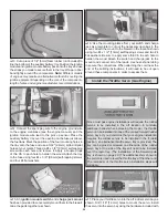
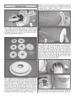
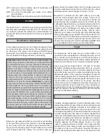
1. If weight is needed at the nose of the model for balancing
purposes, install the auxiliary battery tray. Make a strap by
overlapping the mating ends of the included non-adhesive
hook and loop material by approximately 1" [25mm]. The
total length of the strap you make will be determined by the
size of the receiver battery pack you will be using. Loop the
strap through the slots in the tray that best match the width
of the battery pack. Place the auxiliary battery tray over the
opening on the fuse behind the motor mounting box. Mark
the position of the four mounting holes in the tray onto the
fuse and use a 3/32" [2.4mm] bit to drill pilot holes at your
marks. Thread a #4 x 3/8" [9.5mm] self-tapping screw into
each hole and remove it. Apply a couple drops of thin CA
to each hole to harden the wood. Attach the tray to the fuse
using four #4 x 3/8" [9.5mm] self-tapping screws and four
#4 fl at washers. Cut a piece of 1/4" [6mm] foam rubber (not
included) to match the shape of the battery pack and use
the hook and loop strap to secure the battery pack in place
on the tray.
❏
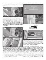
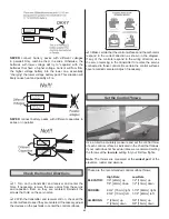
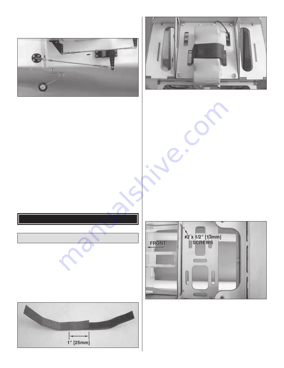
2. If you have installed a brushless motor or gas engine,
you will need to install the aft radio tray. Position the tray
in place as shown and use a 1/16" [1.6mm] drill bit to drill
four holes through the two aft radio tray mounting blocks
and the balsa rail along the fuse former. Thread a #2 x 1/2"
[13mm] self-tapping screw into each hole and remove it.
Apply a couple drops of thin CA to each hole to harden the
wood. Secure the tray with four #2 x 1/2" [13mm] self-tapping
screws and four #2 fl at washers.
Summary of Contents for GPMA1412
Page 52: ......


