background image

Note: This model is covered with a very thin layer of film
which is then painted with a special lightweight paint to
conserve weight. Avoid the use of tape to help position the
fuselage components during assembly. Also, Do Not
attempt to remove any of the trim markings as this will
damage the painted surface beneath.

Also, for simplicity, all of the carbon rods in this ARF are of
the same diameter. When identifying the rods for the
corresponding step, only the lengths are mentioned.

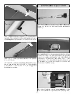
1. Using epoxy, join the two wing halves together,

making sure to align the root sections.

2. Epoxy the 17-3/48" [451 mm] carbon wing joiner tube

into the slot on the bottom of the wing. Make sure it is fully
seated in the slot.

3. Epoxy the foam inserts into the wing slot over the

carbon joiner. Make sure they are fully seated against the
joiner. The foam inserts may not be completely flush with the
bottom of the wing.

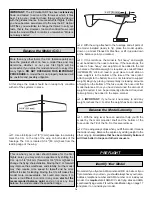
1. Insert the wing into the fuselage. Be sure that the wing

is centered and square by making sure all measurements
are equal as shown in the sketch.

2. Trace along the fuselage sides on the top and bottom

of the wing with a felt-tip pen or a pencil.

3. Slide the wing out just enough to see the entire area

covered by the fuselage. Remove the covering from the wing
using a hobby knife 3/32" [2 mm] inside the marks you made.
Apply a thin layer of epoxy and slide the wing into place. Use the
marks from the previous step to align the wing. Clean up any
excess glue with a paper towel. DO NOT use alcohol or any
other solvent for cleanup as the paint finish will be affected.

Remove 

s

haded area

Join the Wing to the Fuselage

Join the Wing Halves

BUILDING INSTRUCTIONS

7

Summary of Contents for Hellcat ARF

Page 1: ...kit immediately in new and unused condition to the place of purchase To make a warranty claim send the defective part or item to Hobby Services at the address below Hobby Services 3002 N Apollo Dr Su...

Page 2: ...ed combat mount and experience the thrill of close in combat dogfighting With two or more of the Fun Force series combat aircraft you can recreate classic dogfights of history For the latest technical...

Page 3: ...Y use a LiPo approved charger NEVER use a NiCd NiMH peak charger NEVER charge in excess of 4 20V per cell ONLY charge through the charge lead NEVER charge through the discharge lead NEVER charge at cu...

Page 4: ...ger capable of charging 3 cell 11 1V LiPo batteries such as the ElectriFly PolyCharge 1 to 3 cell LiPo charger GPMM3010 must be used If using another charger it must be a LiPo charger or have a LiPo c...

Page 5: ...ler If a hobby shop is not available replacement parts may alsobeorderedfromTowerHobbies atwww towerhobbies com or by calling toll free 800 637 6050 Parts may also be ordered directly from Hobby Servi...

Page 6: ...Support 3002 N Apollo Drive Suite 1 Champaign IL 61822 Telephone 217 398 8970 ext 5 Fax 217 398 7721 E mail airsupport greatplanes com KIT INSPECTION Kit Contents Photographed 1 Fin Rudder 2 Fuselage...

Page 7: ...into the wing slot over the carbon joiner Make sure they are fully seated against the joiner The foam inserts may not be completely flush with the bottom of the wing 1 Insert the wing into the fusela...

Page 8: ...fe CA to glue one of the elevator halves to the carbon elevator rod Then glue the other elevator to the carbon elevator rod Be sure the two halves are even as shown 4 Glue the fin and rudder to the fu...

Page 9: ...lue the aileron to the bearings The rod must freely rotate in the bearings so the aileron must only be glued to the carbon rod 1 Remove the screws and servo arms from all of your servos Enlarge the ho...

Page 10: ...e servo When you glue the extended servo arm be sure it is exactly centered as shown Epoxy the aileron servo into the cutout in the fuselage 1 Locate the two 2 3 4 70 mm prebent aileron pushrods Sligh...

Page 11: ...1 Connect the output wires of your ESC to the motor Check the direction of the motor before permanently installing it 2 Install the ESC as shown using a small section of hook and loop tape Place the h...

Page 12: ...ervo and ESC leads to reach the receiver Use a 6 153 mm extension for the aileron servo lead and a 12 305 mm extension for the ESC Route the servo leads through the pre cut channels in the fuselage to...

Page 13: ...to accurately measure and set the control throw of each control surface as indicated in the chart that follows If your radio does not have dual rates we recommend setting the throws at the low rate o...

Page 14: ...d other maneuvers No matter if you fly at an AMA sanctioned R C club site or if you fly somewhere on your own you should always have your name address telephone number and AMA number on or inside your...

Page 15: ...ect the problem first Look for loose servo connections or broken wires corroded wires on old servo connectors poor solder joints in your battery pack or a defective cell or a damaged receiver crystal...

Page 16: ...umstances may a pilot or other person touch a powered model in flight nor should any part of the model other than the landing gear intentionally touch the ground except while landing 1 Check the C G a...

Page 17: ...odel is a foot or so off the deck cut your throttle and smoothly increase up elevator until it gently touches down on its belly Make sure that you cut your power completely before touchdown or gearbox...

Page 18: ...ny open area a potential flying field Minimal assembly and a factory applied semi scale trim scheme enable you to get to the field fast Carbon fiber tubes and EPS foam construction enable your plane t...

Page 19: ...and Select and then lock in those digitally accurate settings with the Data Input Lever You can save up to four set ups in the 4EXA s memory a big time saver as you add more planes to your personal h...

Page 20: ...____________ Where Purchased _________________________ Date Construction Started __________________ Date Construction Finished _________________ Finished Weight __________________________ Date of Firs...

Reviews: