background image

Prior to balancing the model install the propeller.

The servo tray and receiver location are used to adjust the
center of gravity (C.G.). For now, temporarily position the
battery in the battery compartment and receiver in the radio
compartment, but do not secure them in place. When setting
the C.G. (below), adjust the position of the receiver and
servo tray as needed. Remember to also reposition the
Velcro

® 

and rubber band mounting to properly hold them in

place. Note: Once the Mini Cub ARF is balanced, you may
secure the receiver and glue the servo tray in place.

❏ 

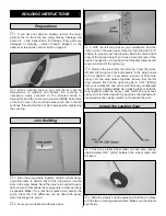
1. Use a felt-tip pen or 1/8" [3mm] wide tape to accurately

mark the C.G. on the bottom of the wing on both sides close
to the fuselage. The recommended C.G. is located 2-1/16"
[52mm] back from the leading edge of the wing.

❏ 

2. With the wing attached to the fuselage and all parts of

the model installed (ready-to-fly), place the model on a
Great Planes C.G. Machine

, or lift it at the balance point

you marked.

❏ 

3. If the tail drops, the model is “tail heavy” and the

battery pack and/or receiver must be shifted forward or
weight must be added to the nose to balance. If the nose
drops, the model is “nose heavy” and the battery pack
and/or receiver must be shifted aft or weight must be added
to the tail to balance. If possible, relocate the battery pack
and receiver to minimize or eliminate any additional ballast
required. Use Great Planes (GPMQ4485) “stick-on” lead if
necessary to add weight. A good place to add stick-on nose
weight is to the firewall (don’t attach weight to the cowl–it is
not intended to support weight). Begin by placing
incrementally increasing amounts of weight on the bottom of
the fuse over the firewall until the model balances. Once you
have determined the amount of weight required, it can be
permanently attached. If required, tail weight may be added
under the stabilizer.

❏ 

4. IMPORTANT: If you found it necessary to add any

weight, recheck the C.G. after the weight has been installed.

❏ 

1. With the wing level, lift the model by the motor

propeller shaft and the bottom of the fuse under the TE of
the fin. Do this several times.

❏ 

2. If one wing always drops when you lift the model, it means

that side is heavy. Balance the airplane by adding weight to the
other wing tip. An airplane that has been laterally balanced will
track better in loops and other maneuvers.

At this stage the model should be in ready-to-fly condition
with all of the systems in place including the motor, landing
gear, covering and paint, and the radio system.

Balance the Model Laterally

This is where your model should balance for the first
flights. Later, you may wish to experiment by shifting the
C.G. up to 1/4" [6.4mm] forward or 1/4" [6.4mm] back to
change the flying characteristics. Moving the C.G. forward
may improve the smoothness and stability, but the model
may then require more speed for takeoff and make it
more difficult to slow for landing. Moving the C.G. aft
makes the model more maneuverable, but could also
cause it to become too difficult to control. In any case,
start at the recommended balance point and do not at
any time balance the model outside the specified range.

More than any other factor, the C.G. (balance point) can
have the greatest effect on how a model flies, and may
determine whether or not your first flight will be
successful. If you value this model and wish to enjoy it for
many flights, DO NOT OVERLOOK THIS IMPORTANT
PROCEDURE. 
A model that is not properly balanced will
be unstable and possibly unflyable.

Balance the Model (C.G.)

Propeller Installation

14

Summary of Contents for J-3 Electri Cub

Page 1: ...immediately in new and unused condition to the place of purchase To make a warranty claim send the defective part or item to Hobby Services at the address below Hobby Services 3002 N Apollo Dr Suite...

Page 2: ...page We urge you to join the AMA Academy of Model Aeronautics and a local R C club The AMA is the governing body of model aviation and membership is required to fly at AMA clubs Though joining the AM...

Page 3: ...n about clubs in your area whose membership includes experienced pilots Remember Take your time and follow the instructions to end up with a well built model that is straight and true This is a partia...

Page 4: ...d to build the Mini Cub ARF Great Planes Pro CA and Epoxy glue are recommended Hobby knife HCAR0105 11 blades HCAR0211 Small T pins HCAR5100 Electric drill and 1 16 1 6mm drill bit Small Phillips and...

Page 5: ...etail prices and shipping and handling charges will apply Illinois and Nevada residents will also be charged sales tax To locate a hobby dealer visit the Hobbico web site at www hobbico com Choose Whe...

Page 6: ...ick Connect Posts 2 2 8 x 5mm Machine Screws 1 Electronic Speed Control 2 Nylon Tie Straps Before starting to build take an inventory of this kit to make sure it is complete and inspect the parts to m...

Page 7: ...paper 3 With the left wing flat on your workbench and the center joint on the wax paper raise the right wing tip 3 3 4 95mm to properly set the dihedral Block the raised right wing at the desired hei...

Page 8: ...he tail skid in place 2 Locate and cut out the four holes to the front and rear of the wing saddle for the dowel rods Insert the wing dowels in the holes and center When centered securely glue them in...

Page 9: ...nd from the gap on the front of the stab Note Be careful not to cut into the balsa stab when removing the covering 5 Mount the wing to the fuse with two of the rubber bands included with this kit Pin...

Page 10: ...ght indentation through the covering or insert the pushrod into the pushrod tubes inside the fuselage and push the pushrods against the covering Cut the covering away from the pushrod exit with a shar...

Page 11: ...r and receiver off Don t cut the pushrods yet This will allow you to adjust the position of the servo tray for balancing 1 Following the motor manufacturer s instructions assemble your motor and gear...

Page 12: ...ength of thread and run it through both guides on one side of the wing Then tie the ends to the guide installed on the fuse Add a small drop of CA to the knot to secure it Do this for both sides Remov...

Page 13: ...diagram If any of the controls respond in the wrong direction use the servo reversing in the transmitter to reverse the servos connected to those controls Be certain the control surfaces have remaine...

Page 14: ...he firewall until the model balances Once you have determined the amount of weight required it can be permanently attached If required tail weight may be added under the stabilizer 4 IMPORTANT If you...

Page 15: ...irst flight of the day With the transmitter antenna collapsed and the receiver and transmitter on you should be able to walk at least 100 away from the model and still have control Have an assistant s...

Page 16: ...y device that explodes burns or propels a projectile of any kind RADIO CONTROL 1 I will have completed a successful radio equipment ground check before the first flight of a new or repaired model 2 I...

Page 17: ...into the pits Remember to take off into the wind When you re ready point the model straight down the runway then gradually advance the throttle As the model gains speed decrease up elevator allowing...

Page 18: ...tle back at the top and make certain you are on the desired rates high low rates A flight plan greatly reduces the chances of crashing your model just because of poor planning and impulsive moves Reme...

Page 19: ...19 FLYING NOTES...

Page 20: ...____________ Where Purchased _________________________ Date Construction Started __________________ Date Construction Finished _________________ Finished Weight __________________________ Date of Firs...

Reviews: