background image

❏ ❏ 

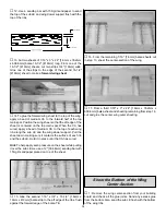
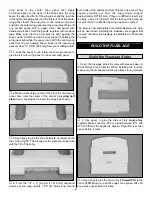
7. Carefully trim or sand the TE of the ribs to match

the angle of the 1/4" [6.4mm] TE stick.

❏ ❏ 

8. Cut a 1/4" x 3/4" x 30" [6.4mm x 19mm x 762mm]

balsa trailing edge 24" [609mm] long. Trim one end of the
24" [609mm] TE to match the angle at rib W5. Pin the TE in
position over the plan. From the remaining TE stick, cut the
TE to fit between the W4 and W5 ribs.

❏ ❏ 

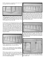
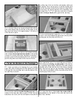
9. With the ribs and wing spar flat against the building

board, use thin CA to glue the bottom main spar and shear
web to the ribs. Do not glue the top main spar to the shear
web or ribs. Before gluing, make sure the shear web is
against the front of the notch in ribs W4 and W5 and rib W4
is set at the correct angle using the dihedral gauge. Check
that the aft end of the ribs and the 1/4" [6.4mm] TE are flat
on the building board. Then, glue the ribs to the TE. Remove
the top spar, run a bead of medium CA along the top of the
shear web and reinstall the top main spar. Finish gluing the
top spar to the ribs.

❏ ❏ 

10. Glue the 3/32" x 1/2" x 30" [2.4mm x 12.7mm x

762mm] sub LE centered on the front of the ribs.

❏  ❏ 

11. Use a sanding bar with 150-grit sandpaper to

sand the top of the sub LE flush with the top of the ribs and
the top of the ribs with the wing spar.

❏ ❏ 

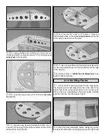
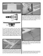
12. From one of the 1/16" x 3" x 30" [1.6mm x 76.2mm

x 762mm] balsa sheets, cut two strips 3/4" [19mm] wide.
Glue one of the strips to the edge of a second 1/16" x 3" x
30" [1.6mm x 76.2mm x 762mm] sheet to make a 3-3/4"
[95mm] wide forward wing sheet.

❏ ❏ 

13. To glue the forward wing sheet to the top of the wing,

apply a bead of medium CA to the forward half of the top
main spar. Position the wing sheet so that the aft edge of the
sheet is centered on the top main spar. When the CA has
cured, apply a bead of medium CA to the top of each wing
rib, and along the sub LE. Pull the sheet down, making sure
it contacts the surface of each rib and the sub LE. Hold it in
place until the CA has cured.

❏ ❏ 

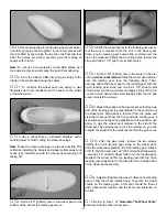
14. Trim the second 1/16" x 3/4" x 30" [1.6mm x 19mm

x 762mm] balsa strip to fit between ribs W5 and W10,
against the front of the TE. Glue the strip to the top of the
ribs and the front of the TE. Trim and glue the remaining strip
between W4 and W5.

❏ ❏ 

15. From a third 1/16" x 3" x 30" [1.6mm x 76.2mm x

762mm] balsa sheet, cut and glue top center sheeting
from ribs W4 to W5.

18

Summary of Contents for Old Timer

Page 1: ...led product By the act of using the user assembled product the user accepts all resulting liability If the buyer is not prepared to accept the liability associated with the use of this product the buy...

Page 2: ...ff 43 Flight 43 Landing 43 TWO VIEW Back Cover Page FUSE WING PLANS Center Pull Out Section The Great Planes Old Timer 40 is a very gentle easy to fly plane The classic lines of the Old Timer 40 will...

Page 3: ...g programs and instructors are available at AMA club sites to help you get started the right way Contact the AMA at the address or toll free phone number below This is the list of hardware and accesso...

Page 4: ...ocker GPMR6060 Denatured alcohol for epoxy clean up Non elastic monofilament or Kevlar fishing line for stab alignment Felt Tip marker TOPQ2510 Razor plane Small metal file Rotary tool such as Dremel...

Page 5: ...you use only 30 minute or 45 minute epoxy because you will need the working time and or the additional strength Photos and sketches are placed before the step they refer to Frequently you can study ph...

Page 6: ...6 DIE PATTERNS...

Page 7: ...7 DIE PATTERNS...

Page 8: ...stick trim and pin the elevator joiner over the plan 5 From one of the 1 4 x 1 2 x 30 6 4mm x 12 7mm x 762mm balsa sticks cut the two elevator LE halves so that they fit tight against the elevator jo...

Page 9: ...the strip onto the previously installed strip Note If you work quickly the previous strip will still be wet on the outside This will accelerate the CA securing the strips to one another immediately I...

Page 10: ...and 220 grit sandpaper to sand the entire top and bottom surface of the stab elevator flat and even Be careful while sanding so that you do not over thin any one particular area of the stab elevator...

Page 11: ...articular area of the fin rudder or gouge the ribs by snagging the sandpaper on them 8 Round all edges of the fin rudder to the shape shown on the cross section on the plan 9 Cut the outer frame betwe...

Page 12: ...after the airplane is covered 6 Lay the rudder over the fuse plan and mark the location for the tailgear wire 7 Drill a 3 32 2 4mm hole 3 4 19mm deep at the centerline of the rudder LE at the mark you...

Page 13: ...tor 4 Lay the rudder over the plan and mark the cutout on the LE for the elevator joiner Use a razor saw or hobby knife to cut the LE for the elevator joiner 5 Temporarily attach the rudder to the fin...

Page 14: ...TE in position over the plan 9 Pin the wing ribs to the building board 10 With the ribs and wing spar flat against the building board use thin CA to glue the bottom main spar and shear web to the ribs...

Page 15: ...Pull the sheet down making sure it contacts the surface of each rib and the sub LE Hold it in place until the CA has cured Hint To help apply even pressure on the sheet while pulling it over the sub...

Page 16: ...the CA has cured apply a bead of medium CA to the top of each wing rib along the sub LE and the wing dowel support Pull the sheet down making sure it contacts the surface of each rib and the sub LE Ho...

Page 17: ...wood main spars so any warps will counteract each other 3 Position one of the main spars over the plan and pin it to the building board Because the wing uses a center shear web the main spar can only...

Page 18: ...d on the front of the ribs 11 Use a sanding bar with 150 grit sandpaper to sand the top of the sub LE flush with the top of the ribs and the top of the ribs with the wing spar 12 From one of the 1 16...

Page 19: ...CA to the bottom of each wing rib and along the sub LE Pull the sheet down making sure it contacts the surface of each rib and the sub LE Hold it in place until the CA has cured 5 Trim the 1 16 x 1 1...

Page 20: ...the wing tip as shown on the plan 17 Use a Power Plane and sanding bar to blend the LE TE and wing tip braces into the wing tip Round the edge of the wing tip 18 Return to step 1 Build The Left Wing P...

Page 21: ...lue the wing bolt plate centered on the top of the wing TE The aft edge of the plate should be flush with the TE of the wing 6 From the 1 4 x 4 6 4mm x 101 6mm hardwood dowel cut two wing dowels 1 7 8...

Page 22: ...side to remove any excess glue and smooth out the joints 8 Go back to step 5 and assemble the second fuse side 9 Place the two fuse sides together and check that they match up all the way around If t...

Page 23: ...he fuse side Do not glue the formers to the fuse side They are only to position the cross braces at this time 17 Draw a line perpendicular to the bottom edge of the fuselage 2 3 4 69 8mm from the aft...

Page 24: ...and pin it to the plan 5 Pull the fuse sides together at former F4 F5 and F6 Tape the sides together and pin the formers to the building board aligning the mark at the bottom of each former with the...

Page 25: ...tray to the firewall fuse sides and formers F2 and F3 12 Glue the die cut 3 ply forward top tray FTT to the back of the firewall fuse sides and former F2 13 Glue the die cut 3 ply instrument panel IP...

Page 26: ...h the top of the sheet If it is not trim the notch slightly until the rail fits properly Use 6 minute epoxy to glue the landing gear rail to the fuse side and the front of former F2 Wipe off any exces...

Page 27: ...50 50 mixture of microballoons and epoxy 10 After the filler has cured cut off the pushrod tubes flush with the fuse side and use a sanding bar to sand the outer pushrod tubes and filler flush with th...

Page 28: ...Important Do not allow the wing to shift during this procedure 4 Remove the wing and use a 17 64 6 7mm drill bit to enlarge the holes in the wing only 5 Use a 1 4 20 tap to cut threads into the wing...

Page 29: ...up with the stab TE and the fin base must be against the stab Trim and sand the top of the fin LE so that it is flush with the top of the aft fuse deck 5 Sight down the fin checking that it is in lin...

Page 30: ...gear rail with the landing gear straps and four 2 x 3 8 screws 1 Trim one matching set of wheel pant halves along the molded cut lines You can use a hobby knife to carefully score along the cut lines...

Page 31: ...retainer over the landing gear see the following step Then securely attach the wheel pant to the landing gear with the nylon landing gear strap and two 2 x 3 8 sheet metal screws Remove the two screw...

Page 32: ...y 1 2 12 7mm square fairing doublers flush with the top of the fairing Sand the doublers flush with the edges of the landing gear fairing 2 Use a sanding bar to round the leading and trailing edge of...

Page 33: ...g it to fully harden before mounting the engine 4 Set the engine in position and mark the firewall for the throttle pushrod inline with the throttle arm Remove the engine and drill a 3 16 hole at the...

Page 34: ...removing the wing 7 Wrap the receiver and receiver battery in 1 4 foam rubber not included 8 Temporarily position the receiver and receiver battery on the fuse bottom Later the receiver battery may b...

Page 35: ...servo and install the brass screw lock pushrod connector on the throttle servo arm and secure it with a nylon retainer 7 Slide the screw lock pushrod connector onto the throttle pushrod Install the t...

Page 36: ...an open structure The procedure that was used to cover the Old Timer 40 uses a template made from paper for the white and transparent blue covering The transparent blue template was drawn approximatel...

Page 37: ...ge slots in the elevator and stab Also cut the covering from the groove for the tailgear wire 2 Reinstall the CA hinges in the elevator without glue INSTALLING CA HINGES The hinge material supplied in...

Page 38: ...Slide a silicone clevis retainer over the pushrod and reinstall the clevises If you removed the servos receiver receiver battery and receiver switch reinstall them 2 Make a strain relief from a cut of...

Page 39: ...tain the control surfaces have remained centered Adjust if necessary Use a Great Planes AccuThrow or a ruler to accurately measure and set the control throw of each control surface as indicated in the...

Page 40: ...IMPORTANT If you found it necessary to add any weight recheck the C G after the weight has been installed No matter if you fly at an AMA sanctioned R C club site or if you fly somewhere on your own yo...

Page 41: ...gravel or sand the propeller may throw such material in your face or eyes Keep your face and body as well as all spectators away from the plane of rotation of the propeller as you start and run the en...

Page 42: ...icone thread locking compound or J B Weld 15 Make sure the fuel lines are connected and are not kinked 16 Use an incidence meter to check the wing for twists and attempt to correct before flying 17 Ba...

Page 43: ...ing various maneuvers and making mental notes or having your assistant write them down of what trim or C G changes may be required to fine tune the model so it flies the way you like Mind your fuel le...

Page 44: ...TWO VIEW DRAWING Use copies of this page to plan your trim scheme...

Page 45: ...B C...

Page 46: ...D A...

Reviews: