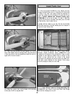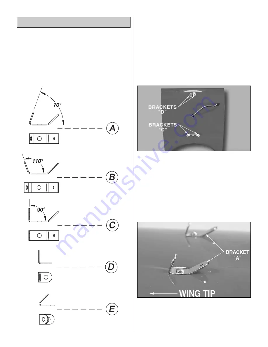
Note: Throughout the rest of the assembly process you
will be installing different types of metal brackets. These
are diagrammed below. Pay close attention to each metal
bracket to make sure you are using the correct one for
each particular application and that they are oriented as
shown in the photographs. Also note that the holes in
each bracket are of a different size. The larger hole allows
the mounting screw to pass through and the smaller hole
is for attachment of the metal clevis.
❏
1. Locate the four predrilled holes in the bottom of the top
wing center section.
IMPORTANT NOTE: IN THE FOLLOWING STEP IT IS VERY
IMPORTANT TO INSTALL THE TWO 90-DEGREE
BRACKETS PROPERLY. THESE BRACKETS HAVE ONE
SIDE THAT IS LONGER THAN THE OTHER. WHEN
INSTALLED CORRECTLY THERE SHOULD BE NO GAP
BETWEEN THESE BRACKETS. IF THERE IS A GAP THEY
ARE INSTALLED WRONG. CHECK THE PHOTOGRAPH
ON PAGE 15, STEP 8 FOR THE PROPER POSITION OF
THESE BRACKETS.
❏
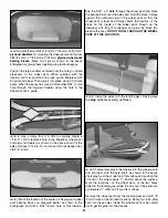
2. Using the technique described on Page 8, install two
90-degree metal brackets (Bracket D, as shown above) into
the pre-drilled holes in the front of the bottom of the top wing
center section with two #4 x 1/2" (13mm) wood screws.
Mount two 90-degree compound bend metal brackets
(Bracket C, as shown above) using two #4 x 1/2" (13mm)
wood screws. The cabane struts and flying wires will attach
to these "C" brackets in a later step.
❏
3. Next locate the four predrilled holes in the two outer
panels of the bottom of the top wing just outboard of the
aileron servos.
❏
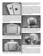
4. Again, using the technique described on Page 8, install
the four 70-degree compound bend metal brackets (Bracket
A, as shown in the diagram) in place (two on each wing
panel) with four #4 x 1/2" (13mm) wood screws as shown in
the photo above. The orientations of these brackets are
shown in the photograph.
70˚ Bracket
90˚ Bracket
90˚
Compound
Bend Bracket
110˚
Compound
Bend Bracket
70˚
Compound
Bend Bracket
Mount the Top Wing
14


