background image

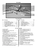
5. Next locate the four predrilled holes in the outer panels of

the top of the bottom wing. See the exact locations and
orientations of the brackets in the following two photographs.

6. Again, using the technique described on Page 8, install

the four 110-degree compound bend metal brackets
(Bracket B as shown above) in place with four #4 x 1/2"
(13mm) wood screws as shown in the photos above.

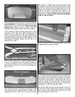
7. Locate the two painted metal cabane struts. Temporarily

and loosely place two 4-40 x 1/2" (13 mm) Socket Head Cap

Screws through the holes in the top of the cabane struts and
hold them both together with two 4-40 Nylon Stop Nuts. Do not
tighten them at this time. Make sure that you have the
orientation of the cabanes correct as shown in the
photographs. Locate the four predrilled holes in the top of the
fuselage. Again, using the same technique described on 
page 8 that you used for attaching the wing brackets, install the
cabane assembly exactly as shown in the photographs above
using four #4 x 1/2" (13mm) wood screws.

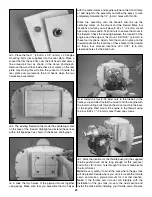
8. Attach the top wing by first removing the two temporary

4-40 x 1/2" (13mm) Socket Head Cap Screws from the top
of the cabane struts and re-inserting them through one
cabane strut hole. Then continue through the two 90 degree
brackets mounted in the top wing, and then back through
the remaining cabane hole. Next, install 4-40 nylon stop
nuts onto the 4-40 x 1/2" (13mm) Socket Head Cap Screws.
Notice in the above photograph that the cabane struts fit on
the outside of the two 90-degree brackets. Do this for both
mounting points.

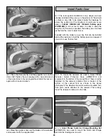
9. Locate the two interplane struts; note that there is a left

and right. This is determined by the contour angles on the
top and bottom of each interplane strut, which allow them to
fit properly against the wing.

With the bottom wing still attached to the fuselage, position
the struts on the outboard sides (toward the wing tips) of the
70-degree compound bend metal brackets on the bottom of
the top wing and the 110-degree compound bend metal
brackets on the top of the bottom wing.

10. For location of the interplane struts on the bottom

wing, measure from the TE of the aileron to the rear tip of

15

Summary of Contents for Pitts Special ARF

Page 1: ...o liability shall be assumed nor accepted for any damage resulting from the use by the user of the final user assembled product By the act of using the user assembled product the user accepts all resu...

Page 2: ...n the Pitts Special in 1942 in Jacksonville Florida The initial Pitts Special powered by a Franklin 90 hp engine flew for the first time during 1944 Over the next 25 years the Pitts Special was availa...

Page 3: ...eck clevises or other connectors often and replace them if they show any signs of wear or fatigue 7 If you are not already an experienced R C pilot you should fly the model only with the help of a com...

Page 4: ...ents will differ based on the manner in which you configure your set up of this model aircraft For example you can set this model aircraft up with two aileron servos only on the bottom wing and mechan...

Page 5: ...he assembly without using any glue then slightly modify or custom fit the part as necessary for the best fit Whenever the term glue is written you should rely upon your experience to decide what type...

Page 6: ...t to firewall and engine to mount 13 4 40 NYLON STOP NUTS for attaching struts cabanes and brackets for tail surface flying wires 10 4 WASHERS for attaching struts and cabanes 6 2 x 1 2 PHILLIPS HEAD...

Page 7: ...ious page Great Planes Product Support Phone 217 398 8970 Fax 217 398 7721 E mail productsupport greatplanes com You can also check our web site at for the latest Pitts Special updates Ordering Replac...

Page 8: ...l a 3 32 2 4mm hole 1 2 13mm deep in the center of each hinge slot to allow the CA to wick in Follow up with a 11 blade to clean out the slots Hint If you have one use a high speed rotary tool to dril...

Page 9: ...or to slip a piece of paper through 6 Apply six drops of thin CA to the top and bottom of each hinge Do not use CA accelerator After the CA has fully hardened test the hinges by pulling on the ailero...

Page 10: ...o arms for the aileron servos are installed so that they point outboard toward the wing tips as shown in the above photograph This is necessary for proper function 12 Use a builder s triangle to estab...

Page 11: ...e wing joiners until you get the proper fit Note The wing joiners are not designed to fit as tightly as possible in order to allow epoxy to flow around the joiners for a more secure and stronger joint...

Page 12: ...wing assembly as shown leaving 1 2 13mm of the dowel extending from the wing You can use rubbing alcohol for any epoxy clean up Do not disturb the wing until the epoxy has fully hardened 1 If you hav...

Page 13: ...te the belly pan and cut the MonoKote from the two holes which allow access for the wing bolts Saturate the exposed wood with thin CA to make it stronger and paint this area after the CA has cured to...

Page 14: ...CHECK THE PHOTOGRAPH ON PAGE 15 STEP 8 FOR THE PROPER POSITION OF THESE BRACKETS 2 Using the technique described on Page 8 install two 90 degree metal brackets Bracket D as shown above into the pre d...

Page 15: ...bove using four 4 x 1 2 13mm wood screws 8 Attach the top wing by first removing the two temporary 4 40 x 1 2 13mm Socket Head Cap Screws from the top of the cabane struts and re inserting them throug...

Page 16: ...the leading edge Trial fit the stab into the stab saddle Check the position of the stab by measuring the distance from the center of the fuse at the tail post to each tip of the stab this distance nee...

Page 17: ...e MonoKote covering 1 8 inside these lines using the same method used on the stab Apply a generous amount of 30 minute epoxy to the fin slot sides and the top of the stab at the bottom of the slot Ins...

Page 18: ...ing away any residue and allow it to fully harden Then re drill the holes to allow the screws to pass through easily Mount the control horns and back plates to the two elevators with eight 4 40 x 3 4...

Page 19: ...he final assembly to prevent them from loosening 10 In order to make the ground steering as positive as possible we are using a 2 56 pushrod extended from the rudder control rod to the tail wheel stee...

Page 20: ...onto the landing gear Carefully align the leading edge of the spat with the leading edge of the landing gear Drill the 3 32 2 4mm holes through the spats and the landing gear in the locations shown i...

Page 21: ...as shown in the photograph and drill a 5 32 4mm hole at this location Slip the 5 32 x 2 axle through the wheel pant and place the bearing block over the axle shaft Hold the block in place against the...

Page 22: ...n of the wheel collars Remove everything from the axle and grind flat spots on the axle for securing the wheel collars After doing this reassemble the wheels and pants with the wheel collars making su...

Page 23: ...t the marks Apply 30 minute epoxy to the four 8 32 blind nuts being careful not to get the glue into the threads and place them into the holes on the back of the firewall Attach the engine mount to th...

Page 24: ...through the process of mounting a typical two stroke engine in the previous steps We will now go through the process of mounting a gas engine using the US Engines 41cc 2 5 Gas Engine USEG0041 Notice...

Page 25: ...5 mm socket head cap screws and 8 32 blind nuts to secure the mount to the firewall Check the spacing between the location of the engine and the edge of the mount Drill 3 16 4 8 mm in these four locat...

Page 26: ...the pressure fitting on the engine muffler 2 Install the fuel tank so the neck fits through the existing hole in the former behind the engine mounting box Be certain that you have installed the tank...

Page 27: ...e with a 3 32 2 4mm drill bit to allow the 2 x 1 2 13mm Phillips head screws to pass through the cowl Do not redrill the pilot hole in the cowl mounting blocks 4 Repeat this process at the locations o...

Page 28: ...er to keep the weight as far forward as possible the battery was mounted just behind the most forward former Included with the model is a ply tray that can be installed behind the fuel tank to hold th...

Page 29: ...location of your receiver you may be able to use a shorter extension here Just make sure it will reach your receiver Glue this solidly into place with thin CA once you have it positioned This modified...

Page 30: ...se connections are now covered and protected as shown in the photographs Please note that if you shrink this material with the wires in place be careful not to over heat the covering and interplane st...

Page 31: ...forward from the tail post of the fuselage to a point 2 1 2 64mm and drill a 1 16 1 6mm hole at these locations on both sides of the fuselage Again use the described procedure on page 8 to install th...

Page 32: ...the bottom of the stab Place the four clevis assemblies on the metal brackets located on both sides of the fin and the bottom of the fuselage Using the same method as you did with the flying wires on...

Page 33: ...E TOP AND BOTTOM WING IS 0 DEGREES WHEN THE STAB IS SET AT 0 DEGREES THE ENGINE THRUST IS ALSO BUILT IN AT 0 DEGREES DOWN AND 2 DEGREES RIGHT 1 Turn on the transmitter and receiver and center the trim...

Page 34: ...odel with your finger tips at the balance point you marked 5 5 3 4 AFT LIMIT FORWARD LIMIT 5 3 4 5 More than any other factor the C G balance point can have the greatest effect on how a model flies an...

Page 35: ...is heavy Balance the airplane by adding weight to the other wing tip An airplane that has been laterally balanced will track better in loops and other maneuvers No matter if you fly at an AMA sanction...

Page 36: ...eller Make certain the glow plug clip or connector is secure so that it will not pop off or otherwise get into the running propeller Make all engine adjustments from behind the rotating propeller The...

Page 37: ...s to close the carburetor throat completely using throttle trim however other methods are acceptable This requirement applies to all glow gas ignition engines regardless of size Section 6 0 RADIO REQU...

Page 38: ...t 4 Extend your receiver antenna and make sure it has a strain relief inside the fuselage to keep tension off the solder joint inside the receiver 5 Balance your model laterally as explained in the in...

Page 39: ...mooth on the elevator stick allowing the model to establish a gentle climb to a safe altitude before turning into the traffic pattern For reassurance and to keep an eye on other traffic it is a good i...

Page 40: ...al note about flying your model Have a goal or flight plan in mind for every flight This can be learning a new maneuver s improving a maneuver s you already know or learning how the model behaves in c...

Reviews: