15
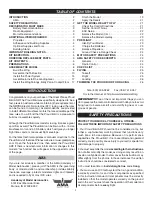
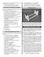
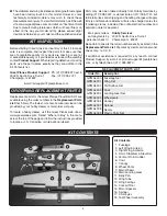
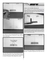
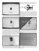
However, the clevis should connect to the second hole from
the base of the control horn and the 90 degree bend should
connect to the hole that is 1/2" [13mm] from the center of the
servo arm. A slight bend in the pushrod at the aft end will
prevent the pushrod from binding in the pushrod tube.
Install the Power System
❏
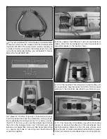
1. The Proud Bird includes eight plywood motor spacers
to accommodate different length motors. The recommended
O.S. .25 motor (OMA-3820-1200) requires the use of three
of these spacers to set the face of the prop adapter at the
correct length of 2-3/4" [70mm] from the fi rewall. The E-Flite
Power 25 1250kV motor does not need any spacers. Use
the spacers to properly space different model motors to the
correct distance from the fi rewall.
❏
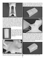
2. The firewall has mounting hole locations for the
recommended O.S. .25 motor (“O” marks) and the E-Flite
Power 25 1250kV motor (“+” marks). Other motors may not
align with these marks and will require you to use the centering
lines on the fi rewall to mark the mounting hole locations for
your motor.
❏
3. 3x35mm screws are included for accommodating motors
requiring all eight motor spacers. If you are using less than eight
spacers, the screws can be cut shorter but this may not be a
necessary step. If you need to cut the screws, thread a blind
nut onto each screw before cutting them. Removing the blind
nut after the cut is made will straighten any damaged threads.
❏
4. Drill 5/32" [4mm] at the marks that match the motor
mounting hole pattern of your motor. We suggest starting with
small pilot holes to ensure accuracy. Use a motor mounting
screw and fl at washer to draw 3mm blind nuts tightly into the
holes you drilled. Apply a drop of glue to the back of each
blind nut to secure them in place.
❏
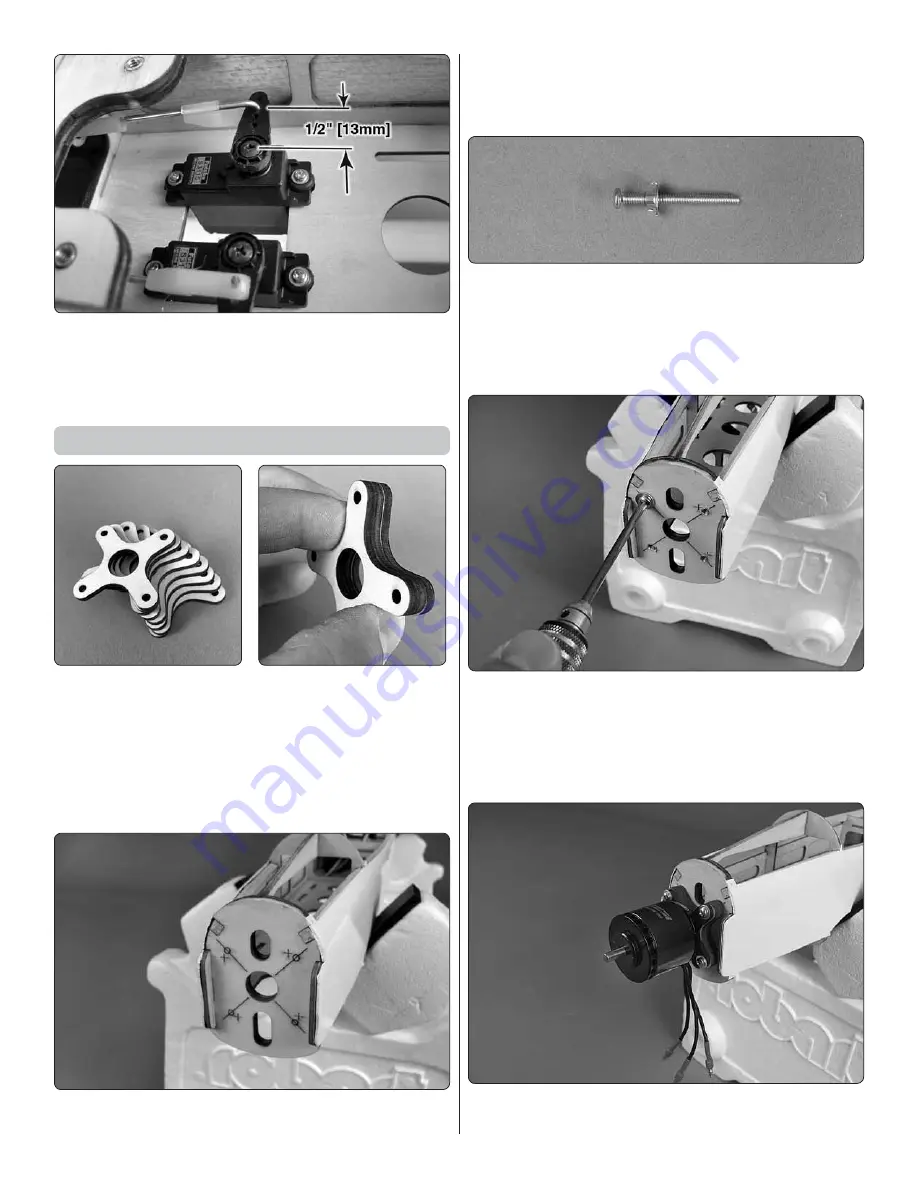
5. Mount your motor using the four 3x35mm motor mount
screws, four 3mm fl at washers and thread locking compound.


